English
 русский
 Español
 عربى
عربىA welding rotator is an industrial positioner that supports and continuously rotates cylindrical or round workpieces — such as pipes, pressure vessels, tanks, and boilers — at a controlled speed during the welding process. It improves weld quality and productivity by enabling automatic circumferential welding in the flat (1G) position, eliminating the need for a welder to reposition around a stationary part. Studies across heavy fabrication shops show that welding rotators reduce manual repositioning time by 40–60% and improve bead consistency compared to fixed-position welding, while reducing welder fatigue on long circumferential seams. For any fabrication facility handling cylindrical weldments above 200 mm in diameter, a welding rotator is one of the highest-return equipment investments available.
What Is a Welding Rotator? Definition, Components, and How It Works
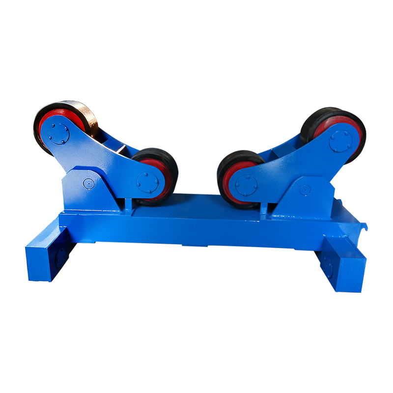
A welding rotator consists of two or more roller assemblies mounted on a rigid frame that cradle a cylindrical workpiece and rotate it at a precisely controlled speed while a welding torch or head remains stationary above or beside the joint. Rather than moving the welding equipment around the part, the rotator moves the part past the welding point — a fundamental shift in approach that enables consistent torch angle, consistent travel speed, and consistent heat input around the entire circumference.
The three core components of any welding rotator system are:
- Drive unit: Contains the motorized rollers powered by an electric motor and gearbox. The drive unit controls rotational speed, typically ranging from 0.1 to 1 RPM on industrial models, and is connected to a speed controller for precise adjustment.
- Idler unit: A passive roller assembly that supports the far end of the workpiece. It follows the rotation driven by the drive unit and is adjustable in width to accommodate different pipe or vessel diameters.
- Control panel / PLC: Governs rotation speed, direction, start/stop, and in advanced models, synchronization with the welding power source for fully automated circumferential welding cycles.
The workpiece rests in the V-groove or flat-surface cradle formed by the roller pairs. The roller angle and spacing determine the contact diameter range the rotator can accommodate. Most standard industrial welding rotators handle diameters from 100 mm to 3,500 mm, with heavy-duty models extending to 6,000 mm and beyond for large vessel fabrication.
Types of Welding Rotators: Which Design Fits Your Application?
There are four main types of welding rotators, each suited to different load capacities, workpiece geometries, and levels of automation. Selecting the wrong type is the most common and costly specification error in fabrication shop setup.
1. Conventional Welding Rotator (Fixed-Angle Rollers)
The conventional welding rotator uses fixed V-angle roller frames and is the most widely used type in general pipe and vessel fabrication. Both drive and idler frames sit at a fixed angle — typically 30° or 45° — creating a stable cradle for round workpieces. Roller spacing is manually adjusted by sliding frames along a base rail to change the supported diameter. Load capacities range from 1 tonne to over 3,000 tonnes per pair. This design is the most cost-effective for facilities working with consistent, standard pipe diameters.
2. Self-Adjusting Welding Rotator (Self-Aligning Rollers)
Self-adjusting welding rotators automatically conform their roller angle to the workpiece diameter, eliminating manual frame repositioning. Each roller assembly uses a pivoting frame that opens or closes under the weight of the workpiece, maintaining optimal contact angle across a wide diameter range — typically 150 mm to 3,000 mm — without any manual adjustment. This dramatically reduces setup time when a shop handles varied pipe sizes throughout the day. The self-aligning design also distributes load more evenly across the roller surface, reducing localized roller wear.
3. Turning Rolls with Tank Head Welding Capability
Heavy-duty turning rolls designed for pressure vessel and storage tank fabrication are built to handle both the cylindrical shell and the end-cap (head) welding operations. These units feature wide-face rubber or polyurethane rollers that provide a non-marring surface for finished or coated vessels, and gear-reduced drives capable of sustaining very slow, precise rotation speeds — as low as 0.01 RPM — for thick-wall submerged arc welding (SAW) passes.
4. Motorized Welding Rotator with CNC / PLC Integration
CNC-integrated welding rotators synchronize workpiece rotation speed directly with welding wire feed rate, travel speed, and power source parameters for fully automated circumferential weld passes. These systems are used in high-volume pipe spool fabrication, offshore platform construction, and automated pressure vessel manufacturing. Speed synchronization accuracy of ±0.5% ensures consistent heat input per unit length — critical for code-compliant welds on pressure-rated components under ASME, EN 13480, or ISO 15614 standards.
Welding Rotator Types Compared
| Type | Diameter Range | Load Capacity | Setup Time | Automation Level | Best Application |
| Conventional | 100 mm – 3,500 mm | 1 – 1,000+ t | Manual (10–20 min) | Basic | Standard pipe, consistent diameters |
| Self-Adjusting | 150 mm – 3,000 mm | 1 – 300 t | Automatic (<2 min) | Moderate | Mixed-diameter pipe spools |
| Heavy-Duty Turning Rolls | 500 mm – 6,000 mm | 10 – 2,000+ t | Manual (varies) | Basic to Moderate | Pressure vessels, storage tanks |
| CNC / PLC Integrated | 100 mm – 4,000 mm | 1 – 500 t | Programmed (<5 min) | Full Automation | High-volume, code-compliant welds |
Caption: Comparison of the four main welding rotator types across diameter range, load capacity, setup time, automation level, and primary industrial application.
Key Specifications to Evaluate When Selecting a Welding Rotator
Load capacity and diameter range are the two non-negotiable specifications — all other features are secondary if the rotator cannot safely support the workpiece at the required size. Here is a structured guide to each critical specification:
Load Capacity
Always specify rotator load capacity at a minimum of 1.25× the heaviest anticipated workpiece weight to provide a safety margin and account for dynamic loads during acceleration and deceleration of rotation. A vessel weighing 8 tonnes requires a rotator rated for at least 10 tonnes. Overloading a welding rotator compresses rollers beyond their bearing capacity, causes frame deflection, and risks catastrophic workpiece rolloff — a serious safety hazard.
Rotation Speed Range
Rotation speed must be matched to the welding process and workpiece diameter to maintain the correct arc travel speed at the joint. The required RPM is calculated as: Travel Speed (mm/min) ÷ (π × Diameter in mm). For example, welding a 600 mm diameter pipe at 400 mm/min travel speed requires approximately 0.21 RPM. Submerged arc welding (SAW) on thick wall vessels may require as little as 0.03–0.08 RPM; TIG root passes on thin-wall stainless pipe may need 0.5–1.5 RPM.
Roller Material
Roller material selection directly affects workpiece surface protection and roller service life. Steel rollers are standard for uncoated structural steel pipe and offer maximum durability. Rubber or polyurethane-coated rollers are required for coated, painted, or polished vessels to prevent surface marring. Polyurethane rollers also provide better grip on smooth surfaces, reducing slip — particularly important on heavy vessels where torque demand is high. Expect to replace polyurethane roller covers every 12–24 months in continuous production use.
Weld Current Grounding
Welding current should never be allowed to pass through the rotator roller bearings — this causes electrolytic pitting of bearing races and rapid failure. Rotators used with processes carrying high amperage (SAW at 600–1,200 A, for example) must have either dedicated earthing brushes on the rotator frame or a separate welding ground clamp applied directly to the workpiece. Many premium rotators include integrated ground brushes that contact the workpiece surface and provide a low-resistance return path, protecting the drive and idler bearings.
Anti-Drift / Axial Restraint
Cylindrical workpieces tend to migrate axially (walk) along the roller axis during rotation — a phenomenon caused by minor misalignment between drive and idler roller centerlines. High-quality rotators address this through angled roller adjustment (toeing in the drive rollers by 1–3°), automatic anti-drift electronic control, or mechanical axial thrust pads. Uncontrolled axial drift moves the weld joint away from the torch, producing off-center welds and potential torch collision with the workpiece end.
Welding Rotator vs. Welding Positioner: What Is the Difference?
A welding rotator and a welding positioner both manipulate workpieces during welding, but they serve fundamentally different geometries and motion requirements. Confusing the two leads to equipment misapplication — a positioner cannot replace a rotator for long cylindrical vessels, and a rotator cannot replace a positioner for flanged or asymmetric assemblies.
| Attribute | Welding Rotator | Welding Positioner |
| Primary Motion | Continuous rotation about horizontal axis | Tilt + rotation about fixed chuck/table |
| Workpiece Shape | Cylindrical / round only | Any shape (flanges, brackets, frames) |
| Weld Joint Type | Circumferential (girth) seams | All joint types (fillet, butt, complex) |
| Max Workpiece Length | Unlimited (multiple idler units) | Limited by chuck overhang capacity |
| Typical Load Range | 1 – 3,000+ tonnes | 0.03 – 100 tonnes |
| Setup for Long Vessels | Add idler units — no length limit | Impractical beyond ~3 m overhang |
| Welding Position Achieved | Flat / 1G (circumferential) | Flat, horizontal, or overhead as needed |
Caption: Side-by-side comparison of welding rotators and welding positioners across seven attributes to clarify correct equipment selection based on workpiece geometry and joint type.
Industries and Applications That Rely on Welding Rotators
Welding rotators are indispensable across every industry that fabricates cylindrical pressure-bearing, structural, or process equipment. Their adoption rate correlates directly with vessel diameter — above 300 mm diameter, manual circumferential welding becomes slow, inconsistent, and ergonomically stressful enough that rotator ROI is typically achieved within 6–18 months of production use.
- Oil and gas: Pipeline girth welds, riser fabrication, subsea manifold spools, and LNG storage tank shell welding. Rotators support submerged arc welding on wall thicknesses from 10 mm to 80 mm on pressure-rated piping under API 1104 and ASME B31.4 standards.
- Pressure vessel manufacturing: ASME Section VIII and PED-compliant vessels — reactors, heat exchangers, condensers, separators — all require controlled circumferential weld passes. Rotators enable consistent preheat maintenance and interpass temperature control by keeping the weld in the flat position throughout multipass sequences.
- Wind energy: Offshore and onshore wind turbine tower sections (typically 4–6 m diameter, 20–30 mm wall thickness) are among the largest rotating welding applications, requiring rotators with capacities exceeding 200–500 tonnes per set.
- Shipbuilding: Propeller shafts, thruster tubes, ballast tanks, and cylindrical hull sections all use rotators in pre-outfitting fabrication shops before onboard installation.
- Mining and aggregate: Ball mills, rotary kilns, drum scrubbers, and conveyor drum fabrication all involve thick-wall cylindrical shells that are practical only with rotator-assisted welding.
- Chemical and petrochemical: Columns, reactors, and process vessels with exotic alloys (duplex stainless, Inconel, titanium) benefit particularly from rotator-enabled flat-position welding, which reduces gravity-induced weld pool disruption in difficult-to-weld materials.
Productivity and Quality Benefits of Using a Welding Rotator
The primary productivity gain from a welding rotator comes from enabling continuous welding arcs rather than stop-and-reposition cycles, but the quality benefits are equally significant and directly reduce rework costs.
Productivity Gains
- Arc-on time increases from 20–35% (manual) to 60–80% with rotator-assisted semiautomatic welding, and up to 90–95% in fully automated systems. A fabrication shop welding 500 mm diameter pipe can complete a full circumferential joint in a single uninterrupted arc versus 4–6 stop-restart sequences in manual welding.
- SAW deposition rates on rotator-supported thick-wall vessels reach 15–25 kg/hr — approximately 5–8× the deposition rate of manual SMAW on the same joint.
- Reduced welder fatigue on long circumferential seams means sustained concentration through multi-hour welding operations, reducing end-of-shift error rates.
Weld Quality Improvements
- Consistent travel speed controlled by the rotator eliminates human variation in torch progression, resulting in uniform bead width and penetration around the full circumference — critical for radiographic and ultrasonic test acceptance.
- Flat (1G) welding position throughout the joint eliminates gravity-induced weld pool sagging that occurs in 2G (horizontal), 5G (fixed pipe), and 6G (inclined pipe) positions, reducing porosity and undercut defect rates by an estimated 35–55% compared to fixed-pipe welding.
- Consistent interpass temperature control is easier to maintain when the weld rotates continuously past a fixed monitoring point, allowing IR sensors or contact thermometers to measure every point of the circumference without repositioning.
Welding Rotator Maintenance: Keeping Equipment Reliable in Production
Regular preventive maintenance on a welding rotator costs a fraction of the downtime and bearing replacement expense caused by neglect — a single failed roller bearing in a 200-tonne rotator can result in 2–3 days of production loss and $5,000–$15,000 in repair costs.
- Daily: Inspect roller surfaces for embedded weld spatter, cuts, or flat spots. Remove spatter with a wire brush or scraper before it hardens and causes surface damage to workpieces or imbalanced rotation. Check that grounding cables are securely attached.
- Weekly: Lubricate drive chain, gearbox, and roller shaft bearings per manufacturer specification. Verify control panel displays accurate speed settings and that emergency stop functions correctly. Inspect roller mounting bolts for vibration loosening.
- Monthly: Check gearbox oil level and condition. Inspect polyurethane or rubber roller covers for cuts, tears, or hardening. Measure roller diameter with a caliper — unequal wear between drive and idler rollers causes speed variation at the workpiece surface.
- Annually: Full drive unit inspection including motor brushes (if DC), gearbox bearing play, and frame weld integrity. Recalibrate speed control against a tachometer reference. Replace roller bearings proactively if operating hours exceed manufacturer's recommended interval — typically 8,000–12,000 operating hours.
Frequently Asked Questions About Welding Rotators
Q1: What is the difference between a welding rotator and a pipe rotator?
The terms are largely interchangeable in common shop usage. A welding rotator is the broader category — it encompasses any powered roller system that rotates a cylindrical workpiece for welding, including pipe, vessels, and drums. "Pipe rotator" is an informal term most often used for lighter-duty units sized specifically for pipeline and pipe spool fabrication. All pipe rotators are welding rotators, but heavy-duty vessel turning rolls designed for tanks and pressure vessels are typically called welding rotators or turning rolls rather than pipe rotators.
Q2: How do I calculate the correct rotator speed for my welding process?
Use the formula: RPM = Travel Speed (mm/min) ÷ (π × Workpiece Diameter in mm). For a 500 mm diameter pipe welded at 350 mm/min travel speed: RPM = 350 ÷ (3.1416 × 500) = 0.223 RPM. For SAW on a 2,000 mm diameter vessel at 250 mm/min: RPM = 250 ÷ (3.1416 × 2,000) = 0.040 RPM. Always verify that your target RPM falls within the rotator's controllable speed range before purchase.
Q3: Can a welding rotator be used for processes other than welding?
Yes. Welding rotators are also widely used for thermal spray coating, painting and powder coating, non-destructive testing (NDT) inspection of cylindrical components, and machining operations such as grinding or polishing cylindrical surfaces. Any process that benefits from uniform rotation of a round workpiece at controlled speed can use the same rotator hardware — the drive and control system is process-agnostic. Some facilities purchase rotators primarily for NDT inspection and use them for welding as a secondary function.
Q4: How many idler units does a welding rotator need for long vessels?
The standard configuration uses one drive unit and one idler unit per supported span. For vessels up to approximately 6–8 meters in length, one drive and one idler set is sufficient. For longer vessels — such as 12–20 meter heat exchanger shells or tower sections — add one additional idler unit for every 4–6 meters of additional length beyond the first span. The critical criterion is that the vessel must not deflect more than 1–2 mm between support points under its own weight, to prevent joint misalignment during rotation.
Q5: What causes a workpiece to "walk" axially on a welding rotator, and how is it prevented?
Axial drift (walking) is caused by a net axial force component arising when drive and idler roller centerlines are not perfectly parallel, or when the workpiece surface is not perfectly cylindrical. It is prevented by: (1) toeing-in the drive rollers by 1–3° so they generate a slight opposing axial force; (2) using anti-drift electronic control that monitors axial position via a sensor and automatically adjusts roller angle; or (3) installing mechanical axial thrust pads or end stops at one end of the rotator frame. Premium self-adjusting rotators typically include electronic anti-drift as a standard feature.
Q6: What safety precautions are essential when operating a welding rotator?
Key safety requirements include: never exceed the rated load capacity — overloading causes roller frame failure and workpiece rolloff; always secure the welding ground cable directly to the workpiece to prevent welding current passing through roller bearings; ensure the floor beneath and around the rotator is clear of personnel when rotating heavy vessels; install mechanical end stops to prevent axial runoff on sloped floors; and never leave a rotating vessel unattended at speed without an automatic emergency stop system active. OSHA 1910.212 (machine guarding) requirements apply to power-driven rotating equipment including welding rotators in U.S. facilities.
Conclusion: Is a Welding Rotator the Right Investment for Your Shop?
For any fabrication shop regularly welding cylindrical components above 200 mm in diameter, a welding rotator delivers measurable ROI within 6–18 months through reduced arc-on time losses, lower rework rates from defect reduction in flat-position welding, and decreased welder fatigue on long-seam work.
The selection decision comes down to four parameters: maximum workpiece weight (drives load capacity spec), diameter range (drives roller spacing and type), required rotation speed range (drives motor and gearbox selection), and production volume (drives the case for self-adjusting versus conventional and for CNC integration). Match those four parameters precisely, apply a 1.25× safety factor to load capacity, and specify roller material to match your workpiece surface requirements.
A well-specified, properly maintained welding rotator is not merely a convenience tool — it is a production-grade manufacturing asset that directly raises the quality ceiling and throughput capacity of any cylindrical fabrication operation. For pressure vessel shops, pipeline fabricators, and wind tower manufacturers especially, it is an essential component of competitive, code-compliant welding production.