 English
 русский
 Español
 عربى
MIG welding is most effective when four conditions line up at the same time: the base metal is clean and dry, the wall thickness sits roughly between 3 mm and 12 mm, the arc is shielded from moving air, and the joint is welded in the flat or horizontal position — or rotated so that it stays there. Remove any one of those conditions and the process still runs, but it quietly stops being the fastest, cleanest and most economical option on the shop floor.
MIG welding, formally gas metal arc welding (GMAW), feeds a continuous consumable wire electrode through a gun while an externally supplied shielding gas protects the molten pool. Because the wire never stops, there is no slag to chip and no electrode to change every few hundred millimetres, which is precisely why the process dominates production welding whenever the working conditions cooperate.
The Four Conditions That Make MIG the Best Choice
Every practical decision about MIG — wire diameter, gas mix, amperage, fixture — comes back to these four structural conditions, and they are worth checking before a welding procedure is written.
Clean, dry metal
Mill scale, oil, paint and moisture burn off inside the arc and turn into porosity. Ten minutes with a grinder is cheaper than a rework ticket.
3 mm to 12 mm wall
Thin enough to fuse through without a bevel, thick enough that the deposition rate pays for itself. Below 1.5 mm the arc becomes unstable; above 12 mm you are into bevels and multi-pass territory.
Still air
Shielding gas is the weakest link. A light cross-draft will strip the gas envelope and leave porosity behind, no matter how good the settings are.
Flat or horizontal position
Gravity works with you in 1G and 2G, so travel speed, penetration and bead appearance all peak there — or you rotate the workpiece instead.
Everything else — inductance, travel angle, contact-tip distance — is a tuning detail that can be corrected with a chart and ten minutes of practice. These four are structural, and no machine setting compensates for a missing one.
Thickness and Material: The MIG Sweet Spot
For carbon steel, MIG is at its best on plate from about 3 mm to 12 mm, and it also handles thin sheet below 3 mm very well when the fit-up is tight and the metal is clean.
| Material thickness | Wire diameter | Shielding gas | Transfer mode |
|---|---|---|---|
| 1.0–3.0 mm sheet | 0.8 mm (0.030 in) | 75% Ar / 25% CO2 | Short-circuit |
| 3.0–6.0 mm plate | 1.0 mm (0.035 in) | 85% Ar / 15% CO2 | Short-circuit or spray |
| 6.0–12.0 mm plate | 1.2 mm (0.045 in) | 90% Ar / 10% CO2 | Spray or pulsed spray |
| 12 mm and above | 1.2–1.6 mm | 90% Ar / 10% CO2 | Pulsed spray, bevelled joint, multi-pass |
Aluminium changes the rules: it needs 100% argon, a push technique to break up the oxide skin, and a spool gun or push-pull torch because the wire is too soft to feed through a long liner. Stainless steel sits between the two and usually wants a tri-mix gas with helium or a small CO2 addition to control fluidity.
Cleanliness and Fit-Up: Where Most MIG Problems Start
Roughly nine out of ten MIG defects trace back to contamination or a joint gap that was too wide for the wire being used — not to the welding machine.
Mill scale and rust do not simply sit on the surface; they absorb heat that should be melting the parent metal, so penetration drops and the operator compensates by winding up the voltage. Oil, paint and cutting fluid boil in the arc and push gas out of the pool, which is why porosity almost always appears on the first pass of a component that was never degreased. Galvanised steel is the hardest case: the zinc coating must be ground back at least 25 mm from the joint line, and even then the fume demands good extraction.
Fit-up matters just as much. A solid wire of 1.2 mm cannot bridge a 3 mm root gap without burning through, so gaps should be held to roughly one wire diameter or less on a square butt joint. If the fabrication tolerance will not allow that, the answer is usually a backing strip or a change of process rather than a change of settings.
Shielding Gas, Draft and Outdoor Reality
MIG is most effective in still air, and shielding gas is the reason.
A 12–20 l/min (25–40 cfh) flow of argon mix can be stripped away by a cross-draft of only 8–10 km/h, which is roughly the speed of a breeze through an open shop door. Turning the flow rate higher than about 20 l/min rarely fixes the problem; the stream becomes turbulent, starts entraining atmospheric air and the porosity gets worse rather than better. Screens, curtains and temporary enclosures solve it in the workshop.
On site, the honest answer is that solid-wire MIG loses to gas-shielded flux-cored wire (FCAW-G), which tolerates wind far better because the slag and flux core help protect the pool. That is why outdoor structural welding and field repair work so rarely run on solid wire.
Position and Rotation: Keeping the Arc in the Flat
MIG delivers its highest deposition rate and its cleanest bead in the flat (1G/1F) and horizontal (2G/2F) positions, because gravity holds the molten pool where the operator wants it.
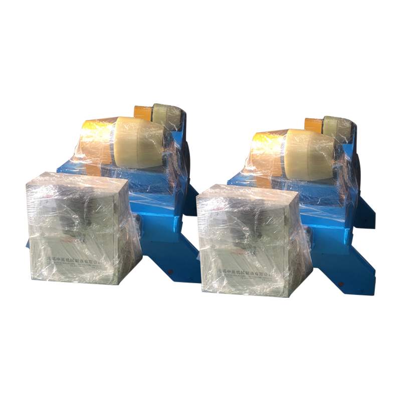
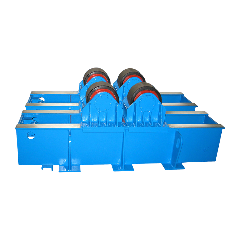
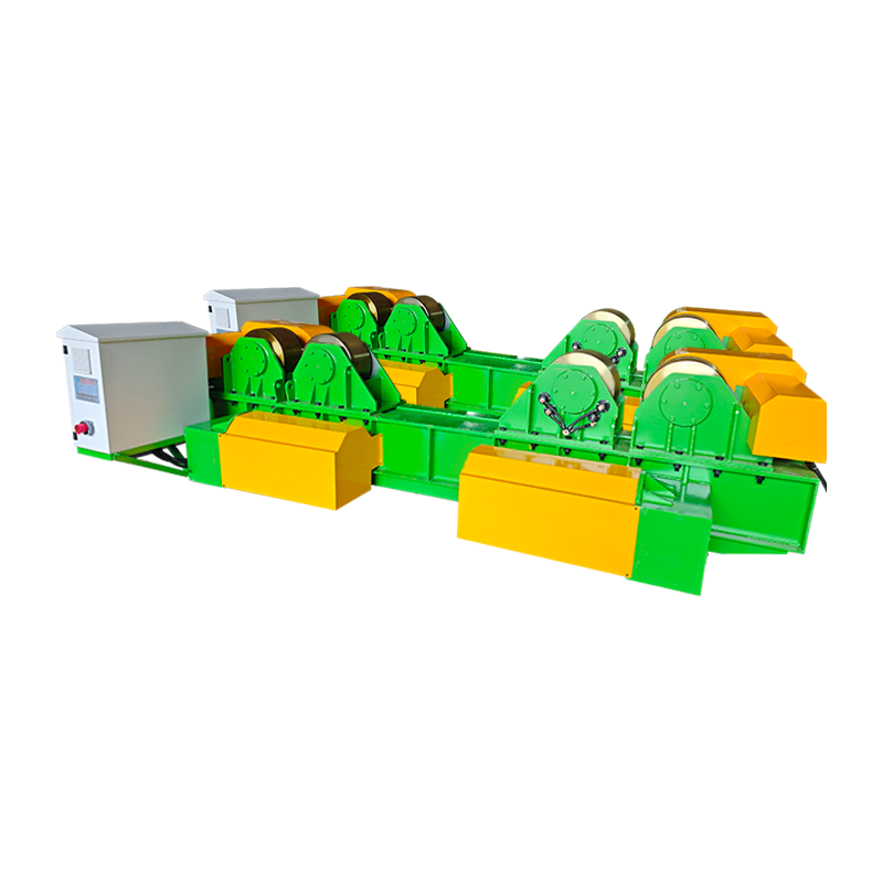
In production, the workpiece is normally rotated instead of the torch. A welding rotator turns a cylinder, vessel or pipe spool at a controlled surface speed so the arc stays permanently in the flat position, which converts a slow, position-dependent job into a repeatable one. For long seams, a unit with anti-drift or powered orbital movement keeps the vessel from creeping axially as it turns, so the seam does not spiral.
 20T Adjustable Welding Rotator with Electric Orbital Movement and Anti-DriftElectric welding rotator for large cylinders, using anti-drift and dual-motor drive to keep circumferential seams stable and repeatable.View Product →
Parts that cannot be turned like a cylinder — brackets, frames, pump housings, valve bodies — are handled on a welding positioner or turntable, which tilts and rotates the work so the joint is presented horizontally. The same rule applies: the fixture, not the welder's wrist, decides whether the weld is made in the flat.
A Pre-Start Checklist That Solves Most MIG Complaints
Before blaming the machine, work through this list in order — in most shops the fault is found in the first five items.
- Confirm electrode-positive (DCEP) polarity for solid wire on steel.
- Set contact-tip-to-work distance at 10–15 mm; longer stick-out drops the amperage and the penetration.
- Set gas flow at 12–20 l/min and check the regulator with the trigger held, not at rest.
- Match wire feed speed and voltage to each other; the arc should sound like steady bacon frying, not crackling or humming.
- Check drive roll tension and liner condition — bird-nesting is a feed problem, not an arc problem.
- Clamp the work return close to the joint, not on a painted frame rail.
- For thin sheet, use a 5–15 degree push angle and slightly higher inductance to soften the short-circuit transfer.
- For heavier plate, drag the gun and increase travel speed until the toes wet out cleanly.
When MIG Is the Wrong Answer
MIG is rarely a bad process, but in a handful of situations another arc process earns its place — and pretending otherwise costs money.
| Process | Best suited to | Practical thickness | Wind tolerance |
|---|---|---|---|
| MIG / GMAW (solid wire, gas) | Clean shop work, sheet and medium plate, high production rate | 1–12 mm | Poor |
| Flux-cored / FCAW-G | Site and outdoor work, thicker sections, structural joints | 6–25 mm | Good |
| Stick / SMAW | Rusty, dirty or wet metal, repairs, confined spaces | 3–20 mm | Excellent |
| TIG / GTAW | Thin sections, root passes, stainless and aluminium where appearance matters | 0.5–6 mm | Poor |
Two further exceptions are worth naming. Extremely thick sections — well beyond 25 mm — are usually faster with submerged arc or flux-cored multi-pass work. And very short welds in awkward positions, where setting up a fixture costs more than the weld itself, often go faster with a stick electrode.
Where MIG Pays Off Most in Production
Tanks, pressure vessels, pipe spools, wind tower sections and H-beams are the environments where MIG welding is most effective at industrial scale, because every one of them can be rotated.
On a vessel or pipe spool, the work is set on powered rollers, the gun is held at a fixed angle, and the machine does the travelling. The same logic drives tower and monopile production, where longitudinal and circumferential seams are welded with the shell turning under a column and boom. In tank and pipe fabrication, this pairing of rotation with a constant torch angle is what turns MIG from a fast manual process into a genuinely repeatable one — the practical effect is covered in more detail in this look at how welding rotators transform metal tank and pipe manufacturing.
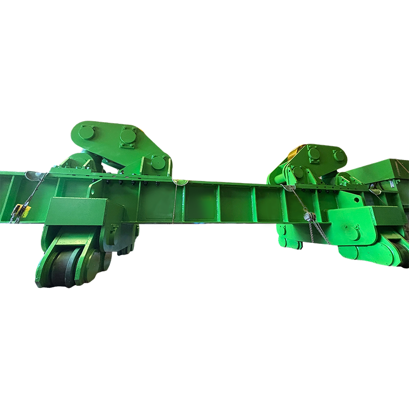
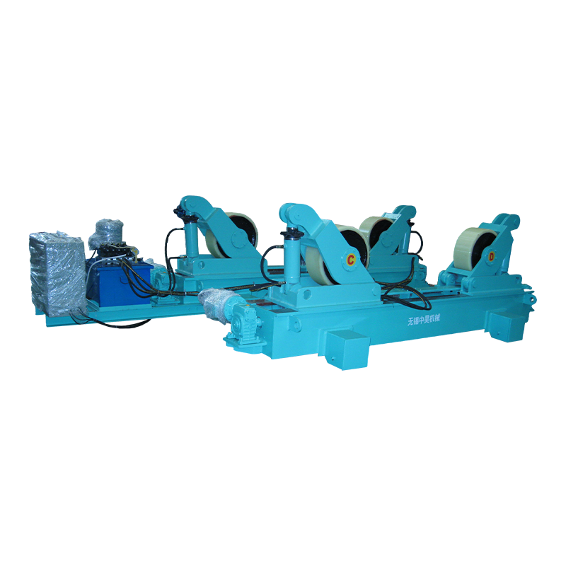
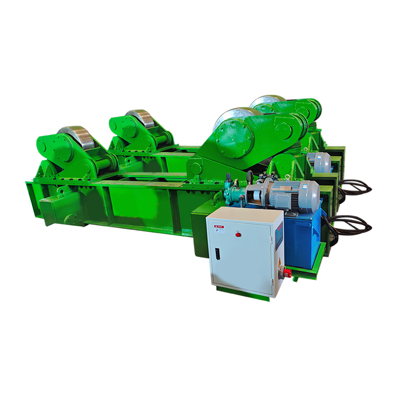
Heavy, awkward workpieces are usually handled on a positioner instead, and large shells that must be aligned before welding benefit from a fit-up rotator with hydraulic lifting and horizontal pushing, which removes crane time from the alignment step.
 3T Conventional Welding Positioner for Heavy-Duty WorkpiecesTilting and rotating turntable for workpieces up to 3000 kg, helping keep welds flat during pressure vessel, pipeline, and structural fabrication.View Product →
 80T Fit-Up Welding Rotator with Hydraulic Horizontal PushingHydraulic fit-up rotator for large cylindrical shells, with adjustable roller base and horizontal pushing to support precise welding assembly.View Product →
The common thread in all of these cases is constant: the arc stays in the flat position, the travel speed is set by a drive rather than by hand, and operators spend their attention on the arc instead of on fighting gravity.
Frequently Asked Questions
Can MIG welding be used outdoors?
Not with solid wire and shielding gas at normal flow rates. Wind above roughly 8–10 km/h breaks the gas envelope, so outdoor work normally switches to gas-shielded flux-cored wire or waits for a screened enclosure to be built.
What is the ideal thickness range for MIG?
For carbon steel, roughly 3 mm to 12 mm is the sweet spot, with sheet down to about 1 mm also workable on short-circuit transfer. Above 12 mm the joint needs a bevel and multiple passes, which erodes MIG's speed advantage.
Why does my MIG weld look porous?
In order of likelihood: contamination such as oil, mill scale or galvanising; a cross-draft stripping the shielding gas; too much gas flow causing turbulence; or a loose regulator fitting drawing air into the line.
Is MIG good for vertical and overhead welding?
It works, but it is no longer at its best. Vertical-up requires lower wire feed speed and a slight weave to control the pool, and overhead welding reduces both deposition rate and operator comfort, so productivity typically drops by a third or more.
Which gas mix gives the best MIG results on mild steel?
A blend of 75–85% argon with the balance CO2 covers most work: higher CO2 improves penetration and wetting on dirty plate, while higher argon smooths the arc and reduces spatter on thin material.
Put plainly, MIG welding is most effective when clean metal of moderate thickness is welded in the flat or horizontal position, indoors, with a stable gas shield and a wire feed speed matched to the voltage. Get those conditions right and the process delivers its full speed, penetration and appearance; fixture the workpiece so the job comes to the arc, and the same conditions hold true for eight hours a shift instead of eight minutes.