 English
 русский
 Español
 عربى
عربىShort answer: a plasma arc is an electrical discharge that travels through a column of ionized gas instead of through solid metal. Constricted by a small nozzle orifice, that column becomes a jet of roughly 15,000–30,000 °C — hot enough to melt every engineering metal — and that single property is why one physical effect can both shear through 40 mm plate and lay a clean root pass in a 6 mm stainless tube.
If you specify, buy or run fabrication equipment, the useful question is rarely what a plasma arc is and almost always which arc you need, at what current, with which gas, and on which machine. What follows is the definition, how the arc forms, the variants that actually appear on a shop floor, where cutting and welding duty diverge, and the specifications worth arguing about with a supplier before you sign a purchase order.
What a Plasma Arc Actually Is
A plasma arc is a sustained electrical discharge in which the conductive path is a gas heated until it splits into free electrons, positive ions and neutral particles. Once the arc has been struck, it needs no mechanical contact between electrode and workpiece.
Two design features set it apart from a TIG or stick arc. The arc is mechanically constricted: a copper nozzle forces the discharge through a narrow orifice, lifting current density and core temperature far above a free-burning arc. And the electrode sits inside the torch body, away from the workpiece, so the shielding gas rather than the arc atmosphere protects the weld pool or the cut face.
Useful working numbers when you compare quotations:
- Core temperature: roughly 15,000–30,000 °C.
- Arc column diameter: about 1–5 mm, set by orifice size, gas flow and current.
- Cutting range: 30–400 A covers thin sheet to around 50 mm carbon steel; high-definition systems reach further on stainless.
- Welding range: micro-plasma from roughly 0.1 mm foil upward; keyhole welding to about 10–12 mm in a single pass.
How the Arc Forms, Step by Step
Formation follows a fixed sequence, and a fault at any step shows up either as a failed start or as an arc that refuses to stay stable.
- Gas establishes the path. Compressed air, nitrogen, argon or an argon-hydrogen mix flows through the torch at a controlled rate and swirl.
- Ionization begins. A high-frequency spark, or a brief electrode-to-nozzle contact, frees the first electrons.
- Current takes over. The DC supply sustains the discharge and the high-frequency circuit switches off.
- Constriction and collimation. The nozzle and gas swirl compress the arc into a concentrated energy spot.
- Transfer to the workpiece. In cutting and plasma arc welding the arc root attaches to the plate and the return path runs through the work lead; before that moment it is only a pilot arc.
The Plasma Arc Variants You Will Meet
Most production faults trace back to confusing these modes. They are not interchangeable, and a double arc is not a process at all — it is damage happening in real time.
| Arc type | Current path | Typical industrial use |
|---|---|---|
| Transferred arc | Electrode to workpiece | Plasma cutting, plasma arc welding, gouging |
| Non-transferred arc | Electrode to nozzle | Plasma spraying, torch heating, gas treatment |
| Pilot arc | Electrode to nozzle at low current | Starting aid; cutting painted, rusty or coated plate |
| Double arc | Parasitic arc from nozzle to workpiece | A fault that erodes the nozzle and weakens the cut |
| Gliding arc | Arc stretched along diverging electrodes in fast gas flow | Surface activation, gas conditioning, laboratory work |
Cutting and Welding: Same Arc, Different Duty
One power supply family can serve both, but the operating window is completely different. Cutting maximises energy density and gas flow so the jet blows molten metal clear of the kerf; welding wants a low-turbulence, tightly controlled column that melts without punching a hole. Mixing the two duty cycles is the fastest way to burn through consumables.
| Parameter | Plasma cutting | Plasma arc welding |
|---|---|---|
| Arc mode | Transferred, high current density | Transferred, constricted, low turbulence |
| Typical current | 30–400 A | 0.1–200 A, micro-plasma to keyhole PAW |
| Gas | Air, nitrogen, oxygen, argon-hydrogen | Argon, argon-hydrogen and helium mixes |
| Material | Any conductive metal | Stainless, titanium, nickel alloys, carbon steel |
| Thickness | 0.5 mm to 50 mm and beyond | 0.1 mm foil to about 12 mm keyhole |
| Key quality issue | Dross, bevel angle, kerf width | Porosity, keyhole collapse, bead profile |
Where Plasma Arcs Earn Their Keep
Anywhere a circular joint must be cut or welded, a mechanised plasma arc wins on repeatability: storage tanks and pressure vessels, process pipe spools, wind tower sections, H-beams and structural steel, and thin sheet for instrument and aerospace work.
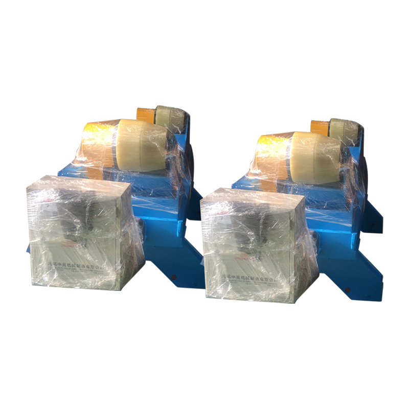
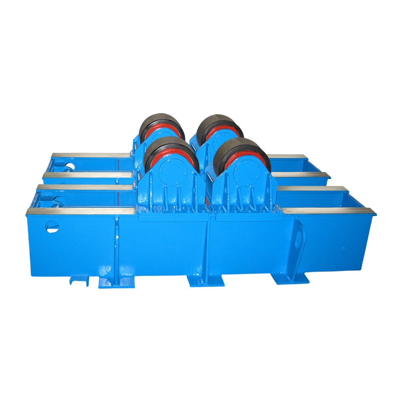
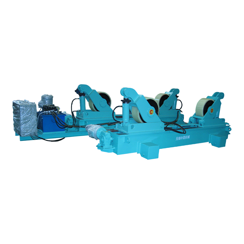
Tank and shell work is the classic case. A plasma or submerged arc head runs along the seam while the shell turns beneath it, so the arc root lands in the same place on every pass. That places the burden on the rotation itself — roller runout, drive smoothness and speed holding all show up directly in bead appearance. Fit-up rotators with hydraulic lifting cover most mid-size vessel diameters; the shop-floor reasoning behind that choice is set out in this note on how welding rotators change tank and pipe manufacturing.
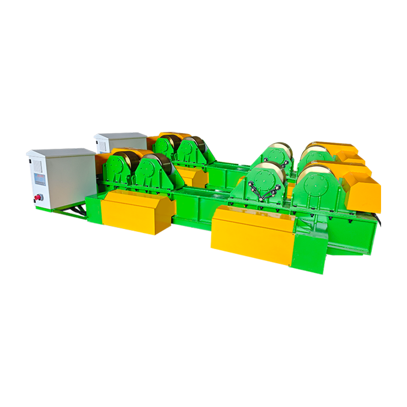 40T Fit-Up Welding Rotator with Hydraulic Lifting and Manual Orbital MovementHandles 40-ton cylindrical workpiece fit-up and welding, with hydraulic height adjustment, manual rail travel, and variable-speed rotation for tank and vessel seams.View Product →
Not every workpiece is cylindrical. For pump housings, frames and valve bodies, a welding positioner turns the joint into the flat or horizontal position a constricted arc prefers, and servo-controlled tilt and rotation hold the angle within a fraction of a degree — which matters when the keyhole is only a few millimetres wide.
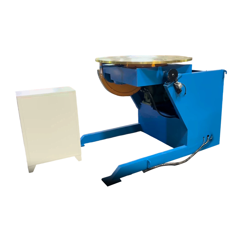 1T Servo-Controlled Welding PositionerOne-ton servo positioner for non-cylindrical parts, providing 0–105° tilt and continuous 360° rotation to hold torch alignment in automated welding.View Product →
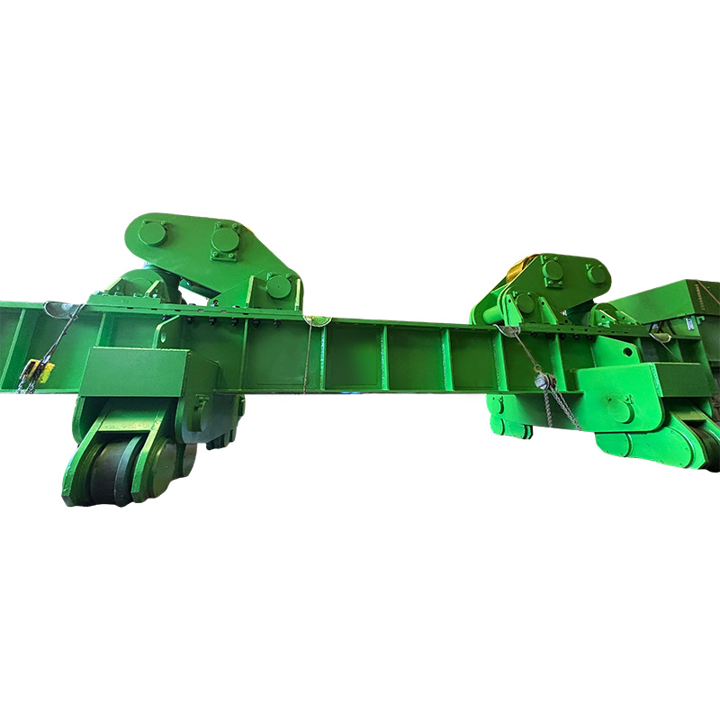
Long straight seams are usually run with the torch carried on a column and boom above a bed or a set of rollers. Electric orbital movement lets the head swing clear for loading and return to the same programmed angle, which shortens setup time between parts.
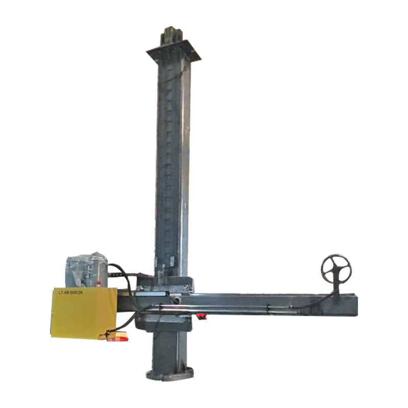 4030 Customized Column & Boom with Electric Orbital MovementCustomized column and boom for automatic welding, with electric orbital movement to position long straight seams and speed setup between parts.View Product →
Wind tower production combines all three: shells are fitted up on rotators, longitudinal seams run under a boom, and the arc process — plasma, submerged arc or a hybrid — is chosen for penetration and travel speed. The process trade-off is covered in this article on welding technology for wind power generation.
What to Check Before You Buy
Plasma arc quality is decided on the specification sheet, not by the demonstration part. Six items matter most.
- Duty cycle at your real current. A 200 A machine rated at 60 percent duty is a different machine from one rated at 100 percent.
- Torch cooling and consumable cost per metre of cut. Water-cooled torches cost more and last considerably longer above roughly 100 A.
- Gas supply and purity. Contamination and pressure droop are two of the most common causes of unstable arcs.
- Motion accuracy. For mechanised welding, look for servo positioning of ±0.1 mm or better and repeatable speed under load.
- Load capacity with margin. Size rotators and positioners for the heaviest workpiece plus tooling, not the average one.
- Certification and documentation. CE marking, test records and a factory visit tell you more than a brochure.
Diagnosing Common Plasma Arc Faults
Most faults have a short list of causes, and the cheapest fix is usually the correct one.
- Dross on the underside of a cut: travel speed too slow, current too low, or standoff excessive.
- Double arcing: worn or incorrect nozzle, insufficient standoff, or moisture in the gas line.
- Short consumable life: poor coolant flow, contaminated gas, or piercing at too low a height.
- Arc wander or keyhole collapse when welding: incorrect gas flow, magnetic build-up in the workpiece, or an unprepared joint gap.
- Porosity in PAW welds: shielding coverage lost, hydrogen pickup, or an arc length that is too long.
Frequently Asked Questions
Is a plasma arc hotter than a TIG arc?
Yes, typically by a factor of two or more. A free-burning TIG arc sits around 10,000–11,000 °C, while a constricted plasma arc reaches 15,000 °C and above. The advantage is not heat alone but concentration: the energy arrives in a narrow column.
Can a plasma arc cut any material?
No. Transferred-arc cutting requires an electrically conductive workpiece, because the current must return through the work lead. Glass, ceramics and most plastics cannot be cut this way.
Why does the torch need a pilot arc?
The pilot arc ionizes the gas path at low current so the main arc can transfer the moment the torch reaches the plate. It also lets the torch start on painted, rusty or coated surfaces that would otherwise break the start.
Is plasma arc welding just a variation of TIG?
No. TIG leaves the arc free to spread, while PAW forces it through a nozzle. The result is a denser column, a keyhole mode for single-pass penetration, and far less sensitivity to arc length.
Does plasma cutting work underwater?
Yes. Underwater cutting reduces noise, fume and ultraviolet radiation, which is why it is common in shipyards and in plants cutting stainless or painted plate.
The Bottom Line
A plasma arc is a constricted discharge through ionized gas, and its two industrial jobs are cutting and welding. Cutting needs maximum energy density and gas flow; welding needs a stable, precisely positioned column. Between the two sit the mechanics — rotators, positioners and column booms that hold the arc root exactly where the procedure says it should be. Get the arc parameters right, then make the motion repeatable, and the process becomes predictable part after part.