 English
 русский
 Español
 عربى
عربىRead the beam designation from left to right. The letter tells you the cross-section family, the first number is the nominal depth in inches, and the number after the multiplication sign is the weight in pounds per foot. For example, W10×30 describes a wide-flange beam with a nominal depth of 10 inches and a weight of 30 pounds per foot. This article explains how to read beam dimensions, what each symbol and number means, and how to avoid the most common sizing mistakes.
What Do Beam Dimensions Mean?
Beam dimensions are read as a compact code: a shape letter, a nominal depth, and a weight per unit length. Structural steel catalogs and drawings use this code to avoid writing a full set of cross-section measurements every time.
In North America, most designations follow the AISC Steel Construction Manual. The usual pattern is shape letter + nominal depth in inches + weight in pounds per foot. For example, W12×26 means a W-shape roughly 12 inches deep that weighs 26 lb/ft. Metric drawings use a similar idea: an IPE 300 beam is an I-profile with a nominal depth of 300 mm, and the exact dimensions are given in a section table.
Standard Steel Beam Shapes
Five shape families cover most rolled steel beams: W, S, HP, M, and H; each family has distinct flange characteristics, and the letter in the designation tells you which family you are working with.
| Shape | Common name | Flange geometry | Typical use | Example |
|---|---|---|---|---|
| W | Wide-flange beam | Flat or nearly flat wide flanges; web is thinner than flanges | Building frames, bridge girders, industrial structures | W12×26 |
| S | American Standard beam | Narrower flanges with tapered inner surfaces | Overhead crane rails, light machinery supports | S8×18.4 |
| HP | H-pile section | Very wide, heavy flanges; depth and flange width are often nearly equal | Foundation piles, deep building columns | HP14×89 |
| M | Miscellaneous section | Dimensions that do not fit W, S, or HP series | Special framing, custom equipment supports | M8×6.5 |
| H | H-beam (generic/imported) | Parallel flanges, similar to W but from metric or offshore specifications | Columns, heavy beams in metric projects | H400×400×13×21 |
W versus S versus H
Choose a W shape when you need strong, wide flanges for bending strength and column capacity. Choose an S shape when the design calls for a compact cross-section and the loads are moderate. The H designation usually appears in metric drawings and behaves similarly to a W shape; always confirm whether the drawing uses imperial or metric dimensions before you order material.
Key Beam Dimensions
The dimensions that matter most are depth, flange width, web thickness, flange thickness, fillet radius, and length. The depth and weight in the designation are enough for ordering, but welding, bolting, and fit-up decisions depend on these exact values.
- Depth (D): total distance from the outer face of the top flange to the outer face of the bottom flange.
- Flange width (bf): total width of the top or bottom flange, measured perpendicular to the web.
- Web thickness (tw): thickness of the vertical web plate between the flanges.
- Flange thickness (tf): thickness of a single flange at the outer face.
- Fillet radius (r): curved transition between web and flanges; important for weld access and fatigue performance.
- Length (L): overall beam length, usually specified separately from the cross-section designation.
Nominal dimensions are not guaranteed exact. Rolling tolerances such as ASTM A6 allow slight variations in depth, flange width, and thickness; practical fabrication always checks actual dimensions before machining or welding.
How to Read a Beam Dimension Notation
Read beam notation from left to right, starting with the shape family, then the nominal depth, then the weight per foot. The order of the numbers is consistent, so you can decode most rolled-beam designations quickly.
- W 27 × 178 — W-shape, nominal depth 27 inches, 178 lb/ft. The actual depth is usually close to 27 inches but not exactly 27 inches.
- S 24 × 121 — American Standard shape, nominal depth 24 inches, 121 lb/ft.
- HP 14 × 89 — H-pile section, nominal depth 14 inches, 89 lb/ft.
When a drawing includes a length, such as W12×26×20’-0”, the last number is the total beam length ordered or erected. For metric material, dimensions are usually given in millimetres and kilograms per metre, for example IPE 300 or HEA 200.
Reading Beam Schedules on Drawings
Beam schedules list every beam in a project with a mark, a size, a length, and a material grade; always cross-reference the mark before ordering or fabricating. The mark on the plan view connects a specific member to its row in the schedule.
| Mark | Size | Length | Material | Remark |
|---|---|---|---|---|
| B1 | W12×26 | 20’-0” | ASTM A992 | Top flange braced |
| B2 | W18×35 | 30’-0” | ASTM A992 | Camber 3/4” |
| B3 | S8×18.4 | 12’-0” | ASTM A36 | Crane rail support |
If you ignore the mark, two beams with similar sizes but different lengths or materials can be mixed during procurement. Check the schedule before cutting, drilling, or welding anything.
How Beam Dimensions Affect Welding and Fabrication
Larger beam dimensions require more weld passes, greater heat input, and more careful distortion control. A deeper and thicker section has more weld metal to deposit, which directly affects joint preparation, preheat, and pass sequence.
Thick flanges may need beveling to achieve full penetration, while long webs create continuous fillet welds that can pull the beam out of straightness. Reading dimensions correctly gives the welder a clear idea of the groove area, the heat input required, and the amount of restraint needed to keep a long beam straight. Because long, heavy beams are difficult to rotate by hand, many large metal structure manufacturers are moving toward automated welding.
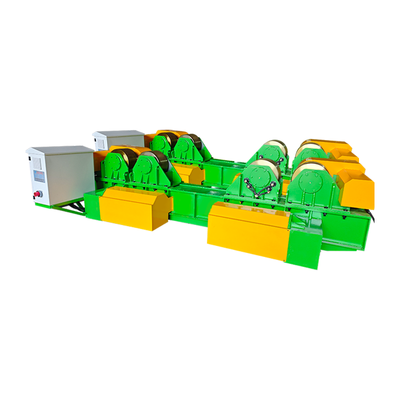
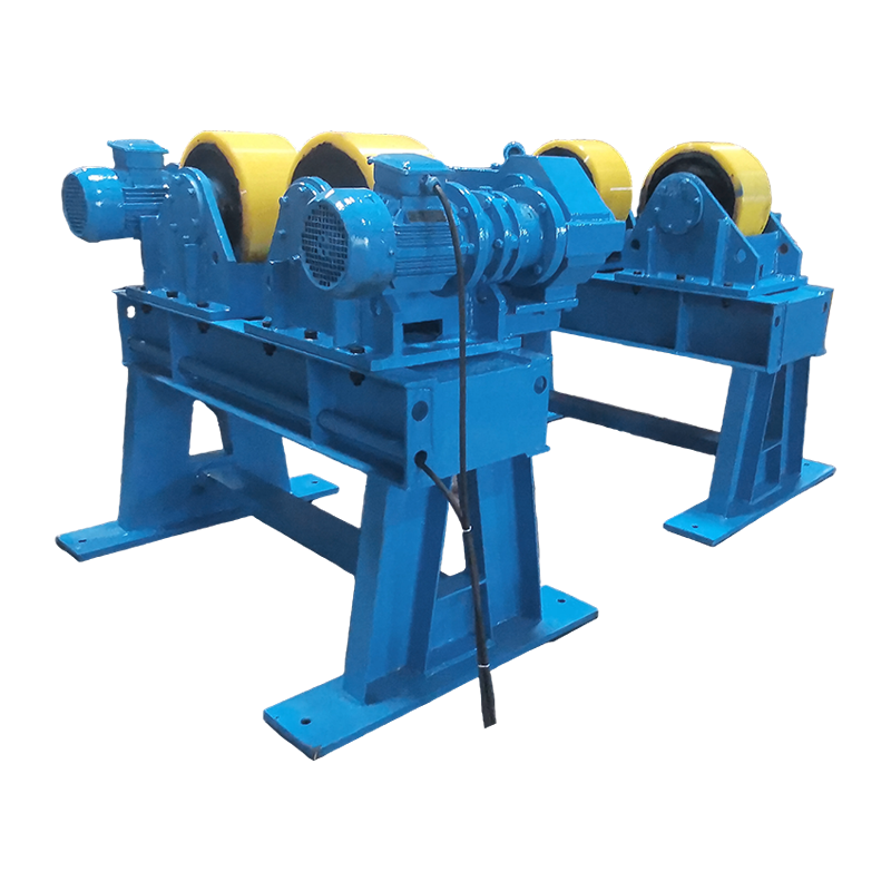
To turn a fabricated beam assembly to a convenient welding angle, a double-column welding positioner can handle heavy sections with precise rotation.
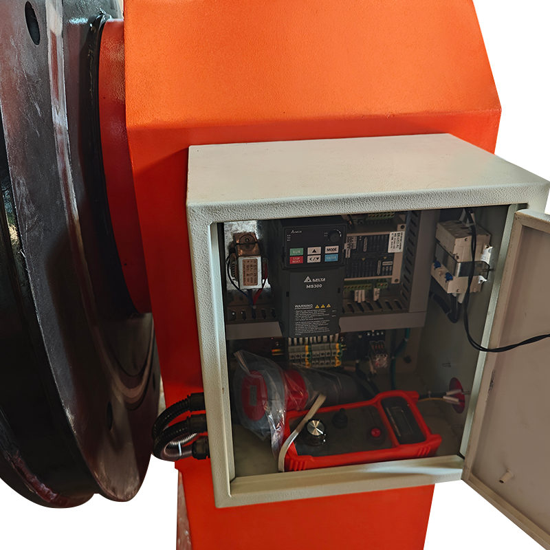 2T Double Column Welding Positioner for Heavy Beam RotationThis double-column positioner is suited for those awkward heavy assemblies that need stable, precise rotation. It supports flat-position welding on steel beams, helping to cut defects and improve productivity.View Product →
Equipment for Handling and Welding Steel Beams
The right positioning equipment lets you weld steel beams in the flat position, which reduces weld defects and increases productivity. Flat-position welding is easier to control, requires less grinding, and produces more consistent reinforcement.
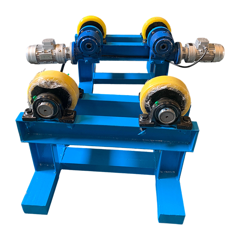
For lighter assemblies that need tilting or continuous rotation during fillet welding, a servo-controlled positioner offers low-speed control and stable support.
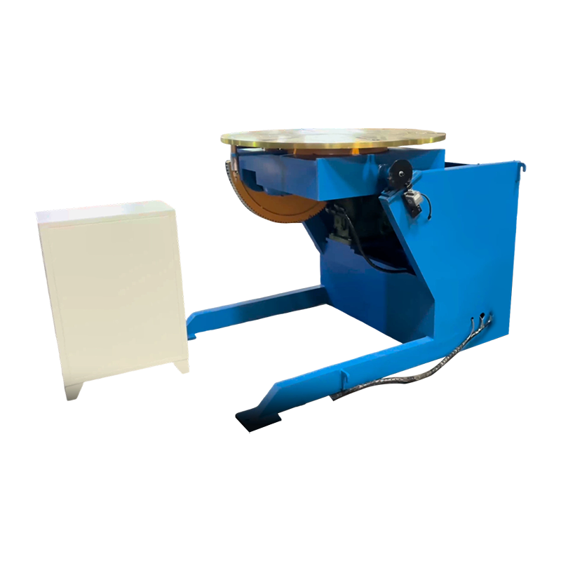 1T Servo-Controlled Welding Positioner for Fillet WeldsA servo-controlled positioner designed for lighter assemblies requiring tilting or continuous rotation during fillet welding. It provides low-speed control and stable support, making it useful for precise weld placement.View Product →
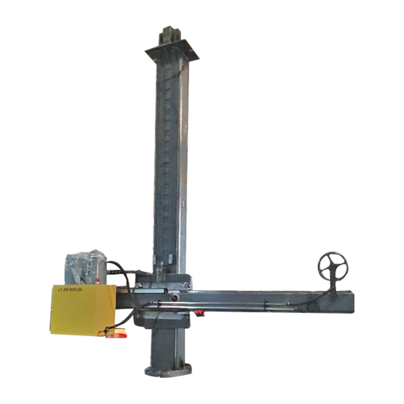
For long longitudinal seams, a column-and-boom system supports the welding head along the beam while the work stays in place. These automated setups are often grouped under welding manipulator systems and are commonly used with submerged arc or flux-cored processes.
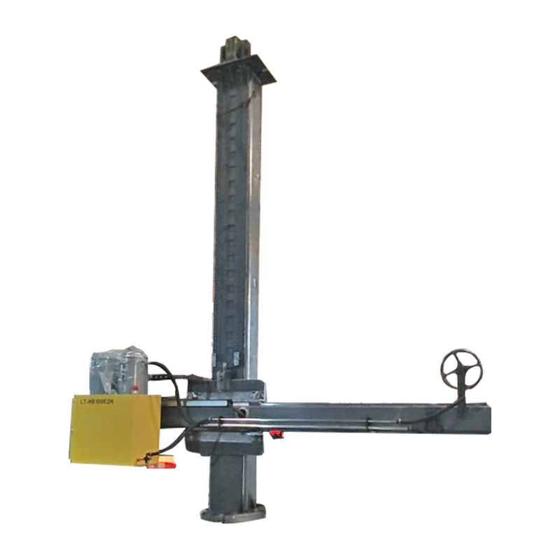 4030 Customized Column and Boom for Longitudinal SeamsThis customized column-and-boom system keeps the welding head aligned along long seams while the workpiece stays put. It works with submerged arc or flux-cored processes, supporting automated setups that improve weld consistency.View Product →
Common Mistakes When Reading Beam Dimensions
Most reading errors come from confusing nominal depth with actual depth, flipping flange width and depth, or mixing imperial and metric units. These mistakes can cause the wrong beam to be ordered, the wrong weld preparation to be cut, or an unsafe connection to be fabricated.
- Confusing weight per foot with total weight. W10×30 means 30 lb per foot, not 30 lb total. Multiply by the length to get the total beam weight.
- Assuming the first number is the exact depth. The designation gives a nominal depth. The actual depth can be several tenths of an inch different, so always verify against the section table.
- Mixing W and S shapes. W flanges are wide and flat; S flanges are narrower and tapered. They are not interchangeable without checking the section properties.
- Reading a metric drawing as imperial. An IPE 300 beam is 300 mm deep, not 300 inches. Check the units before ordering material.
- Ignoring rolling tolerances. Actual thickness and width can vary within the tolerance zone. Measure the section before building weld fixtures or fitting connections.
Frequently Asked Questions
Here are direct answers to common questions about beam dimensions.
What does W10×30 mean?
W10×30 identifies a wide-flange beam with a nominal depth of 10 inches and a weight of 30 pounds per foot. The exact depth of a W10×30 is close to 10.5 inches, depending on the rolling table.
Is the depth shown in a beam designation exact?
No. The number before the multiplication sign is a nominal value. Always check the section table for actual depth, flange width, and thickness before cutting connections.
How do I convert metric beam dimensions to imperial?
Divide millimetres by 25.4 to get inches, and multiply kilograms per metre by 0.672 to get pounds per foot. If possible, use a section table that lists both systems so you do not round incorrectly.
Reading beam dimensions is a matter of recognizing a small code system: shape letter, nominal depth, and weight per foot. Use that code together with the beam schedule and dimension table, verify actual measurements, and the risk of ordering or welding the wrong member drops dramatically.