 English
 русский
 Español
 عربى
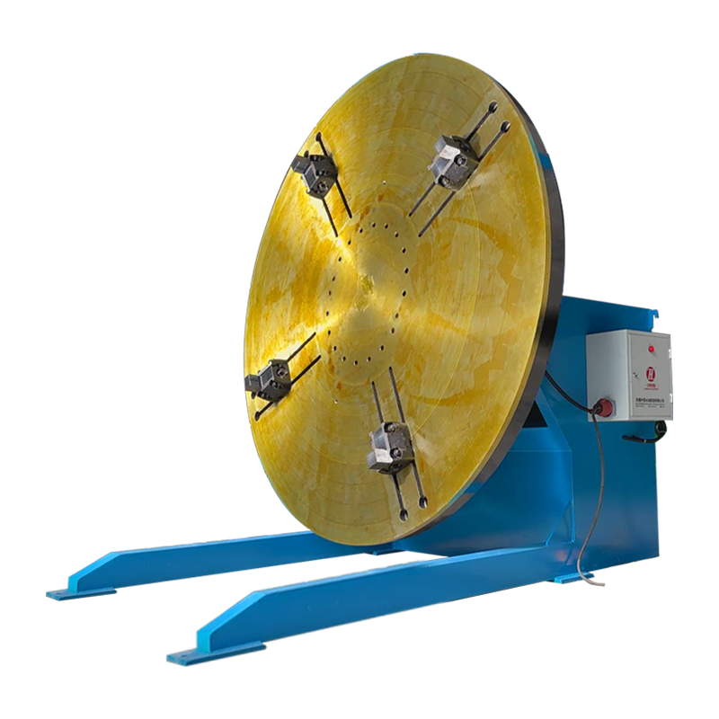
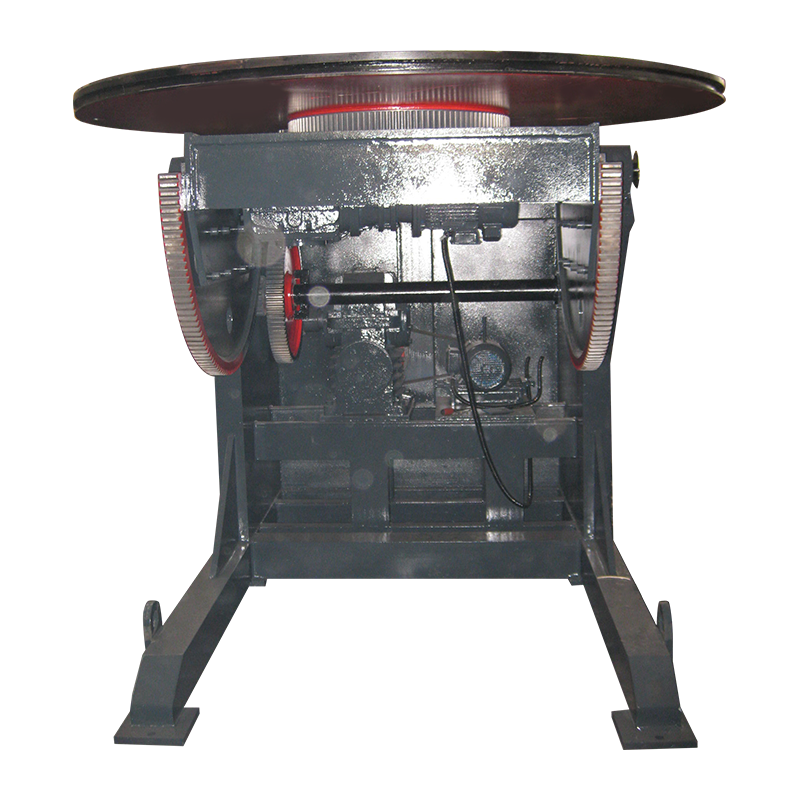
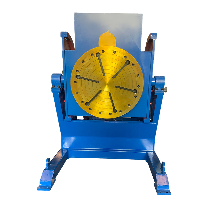
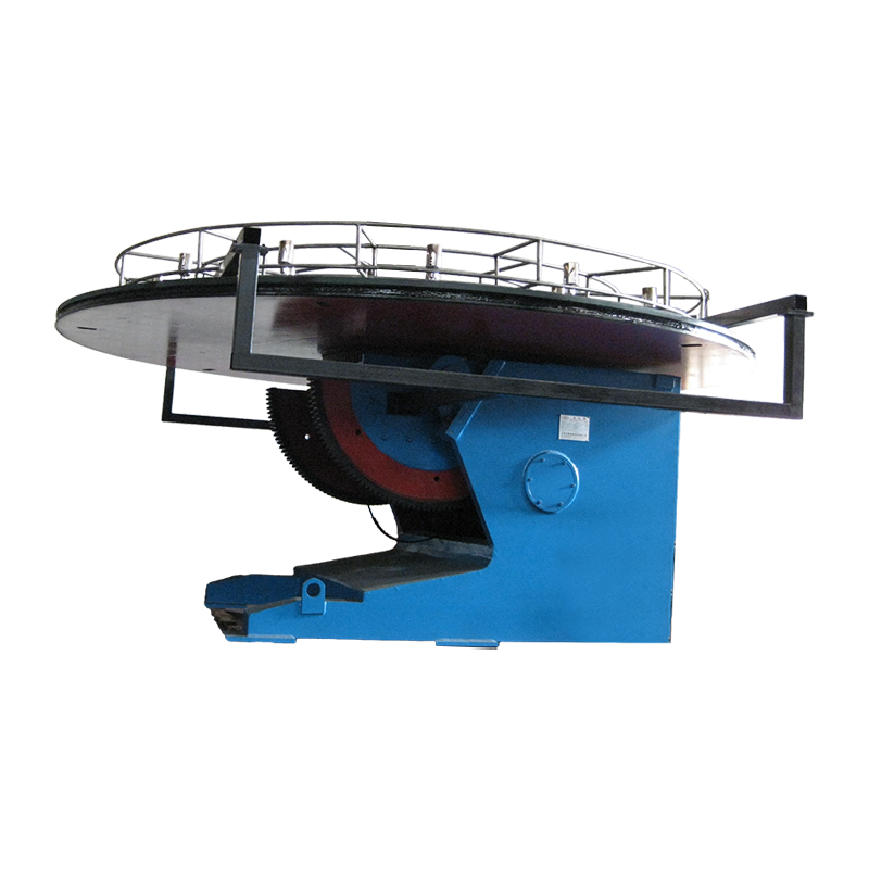
A positioner's nameplate load rating tells you what its spindle can carry. It does not tell you whether the workpiece will hold concentricity at 0.5 rpm, whether the ground path will survive 300 A of welding current, or whether the pendant will accept the fixture you already own. Those questions are answered by welding positioner accessories: the chuck, faceplate, jaws, trunnion rings, drive package, rotary ground and control hardware that sit between the machine and the weld.
The rule we use on the shop floor is simple — size the accessories first, then confirm the positioner has the torque, tilt range and bore sizes to support them. Buyers who start from the load rating alone usually end up purchasing the accessory set twice, once wrong and once right.
What Counts as a Welding Positioner Accessory
Anything that changes how a workpiece is gripped, indexed, powered or protected counts as an accessory, and that list is longer than most purchase orders suggest.
- Workholding: three-jaw and four-jaw chucks, soft jaws, faceplates, T-slotted tables, angle plates, vee blocks, locator pins, quick-clamp kits.
- Motion and drive: servo motors and drives, planetary or backlash-free reducers, brakes, rotary encoders, home and limit switches.
- Control and interface: pendant stations, foot pedals, dual-station selectors, PLC and robot interface modules, E-stop relays.
- Electrical: rotary grounding assemblies, slip rings, welding cable swivels, torch brackets, cable track and festoon systems.
- Process utilities: gas rotary unions, coolant unions, water-cooled cable connectors, fume extraction arms.
The first group is what most people mean by "accessories." The other four are what actually cause unscheduled downtime.
Why the Accessory List Decides the Positioner's Real Capacity
A 2 t positioner fitted with a heavy chuck, a tall jaw stack and a workpiece offset 300 mm from the spindle face is no longer a 2 t positioner in practice, because tilt torque scales with radius while the bearing and gearbox ratings do not.
Two numbers matter more than the headline load. The first is overhung load at the spindle face — the weight multiplied by its distance from the bearing. The second is holding torque during welding, when gravity, cable pull and arc force all act at once. Keep roughly 1.5× torque margin on the drive and the machine will hold position without hunting.
| Accessory group | What it controls | Spec to confirm | Typical symptom of mismatch |
|---|---|---|---|
| Chuck or faceplate | Grip and concentricity | Jaw stroke, through-hole, runout | Workpiece creeps, seam wanders |
| Jaws and soft jaws | Contact area and marking | Jaw height, serration, material | Slip at speed, distortion on thin wall |
| Servo drive and encoder | Index accuracy and repeatability | Torque margin, resolution, backlash | Drift and hunting mid-pass |
| Rotary ground | Return path for weld current | Current rating, duty cycle, rpm | Arcing inside bearings, false weld defects |
| Cable swivel or slip ring | Cable wrap and service life | Conductors, amps, speed limit | Cable fatigue and short circuits |
| Gas or coolant union | Continuous rotation of utilities | Pressure, bore, seal type | Leaks, porosity, coolant on the joint |
Matching Workholding to Workpiece Geometry
Round parts want a chuck or a set of rolls, boxed fabrications want a T-slotted table with angle plates, and anything asymmetric wants counterweights plus a tailstock — the geometry, not the budget, sets the order.
Round and symmetric workpieces
A self-centering three-jaw chuck is the fastest option for flanges, pipe spools and valve bodies because it centres in one movement; a four-jaw independent chuck is the right call when the centre of gravity sits off-axis or the part is a rough casting. Check jaw stroke against the actual diameter range you run, not the catalogue maximum, and confirm the through-hole diameter if you plan to feed welding cable or a purge line through the spindle.
Box, frame and fabricated parts
For H-beams, machine frames and weldments, a T-slotted table with slotted angle plates gives you adjustment in two axes; a chuck cannot hold a square corner without shimming that costs setup time. Table flatness and T-slot spacing matter more than table thickness here, because clamps work best when the bolt lands where the slot actually is.
Off-centre and long parts
Counterweights and a tailstock or steady rest convert an unstable setup into a stable one. On long shafts, support at both ends also protects the tilt gearbox from a bending moment it was never sized for.
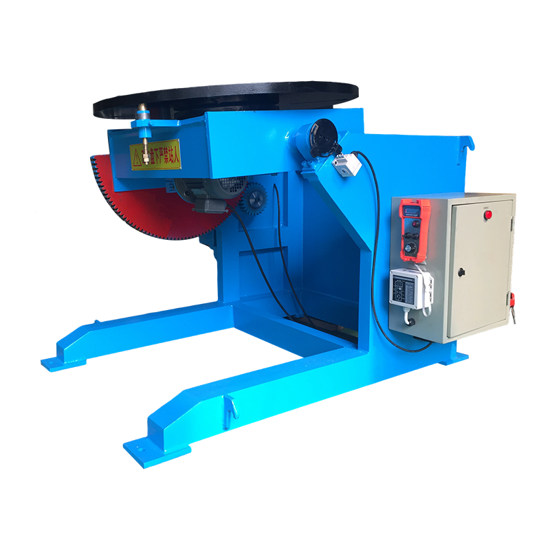
 3T Conventional Welding Positioner with Vertical Lathe ChucksA 3-ton positioner with additional vertical lathe chucks that expand clamping range for cylindrical or irregular workpieces and support stable tilt-and-rotate welding.View Product →
Controls and Electrical Accessories: Where Index Accuracy Comes From
Index accuracy is a system property — motor, reducer, encoder and controller have to be matched, not merely connected.
A variable-frequency drive on an induction motor gives you rotation, but a closed-loop servo package gives you a holding position, programmable angles such as 90° and 180°, and repeatability measured in arc-minutes. For repetitive circular seams, the servo route usually pays back through reduced rework rather than through speed.
Buy the ergonomics deliberately. A foot pedal frees both hands for torch angle and filler, which matters more than most control features on short, fussy welds. A pendant earns its place when the operator needs to jog, set zero and store offset positions without walking to the cabinet. Whatever you choose, confirm the ingress protection class against spatter and grinding dust, and check that the interface voltage matches the plant standard before the crate ships.
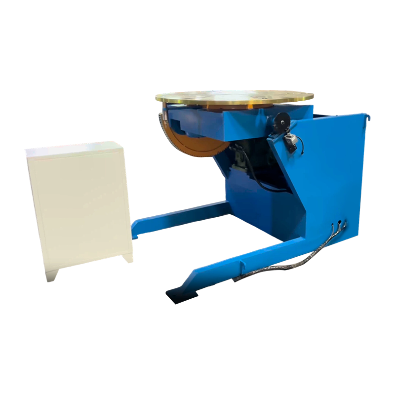 1T Servo-Controlled Welding Positioner for Precise PositioningA 1-ton servo positioner with 0–105° tilt, 360° rotation and precise speed control for automated cells that need repeatable weld positioning.View Product →
Grounding and Cable Management: The Accessories That Prevent Bearing Damage
The welding return path is an accessory decision, and skipping it is the most expensive shortcut in a positioner cell.
If current returns through the spindle bearings, it arcs across lubricated contact surfaces and destroys them quietly. A dedicated rotary ground sized above your maximum welding current, rated for continuous rotation and insulated from the bearing path, keeps current where it belongs. Pair it with a cable swivel rated for the same amperage so the torch lead does not wind up around the spindle after twenty revolutions. On cells running mixed processes, add a gas rotary union and a coolant union with seals rated for the rotation speed you actually use, not the speed in the brochure.
Retrofit and Compatibility Risks Worth Checking Before You Order
Most retrofit problems are dimensional, and all of them are cheaper to find on a drawing than on the shop floor.
- Spindle interface: bolt circle, pilot diameter, keyway and taper must match the new chuck or faceplate, not come close.
- Drive electronics: encoder type, cable pinout and control voltage rarely transfer between generations.
- Torque margin: an accessory that adds mass or offset reduces the usable load on the existing gearbox.
- Runout after mounting: measure it, because a chuck seated on a burr will index perfectly and still weld off-centre.
Where throughput rather than holding accuracy is the actual constraint, it is worth reading how a positioner fits into a broader efficiency picture in our note on addressing welding inefficiency with positioners, then comparing that logic against your own cycle times.
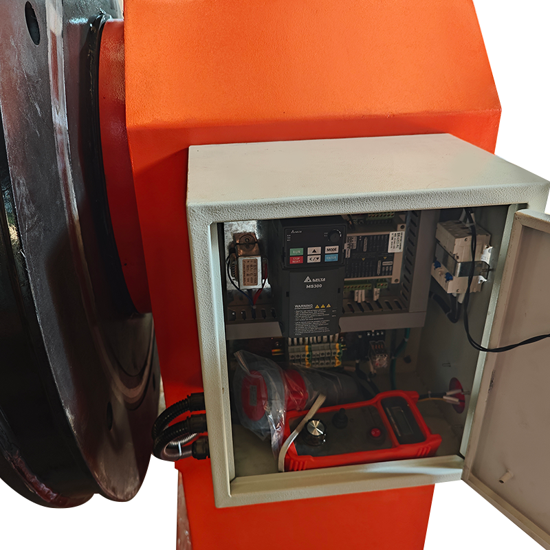 2T Double Column Welding Positioner with Lifting WorktableA 2-ton double-column positioner with stepless rotation and a lifting worktable for stable support of large, eccentric workpieces in automated welding setups.View Product →
A Buyer's Checklist for Positioner Accessories
Confirm these eight items in writing before the order is released; each one has caused a delayed commissioning on someone's floor.
Workpiece data
Weight, centre of gravity offset, diameter or envelope, and the thinnest wall you will clamp.
Spindle interface
Bolt circle, pilot diameter, through-hole and taper, measured rather than recalled.
Duty and speed
Rotations per shift, welding current, and the rpm the accessory must survive continuously.
- Rated load versus actual overhung load at the spindle face.
- Jaw stroke or table size against the real part family, including oversize jobs.
- Through-hole diameter for cable, purge or coolant routing.
- Rotary ground current rating and duty cycle.
- Encoder resolution, gearbox backlash and repeatability in arc-minutes.
- Control interface voltage, protocol and E-stop arrangement.
- Ingress protection and spatter shielding for the environment.
- Documentation, spare jaws and seal kits for the first year of operation.
Our own range of welding positioners and turntables is built around this order of questions, from 30 kg bench units to 300 t custom heads, so accessory selection and machine sizing are quoted together rather than in sequence.
Frequently Asked Questions
Do I need a chuck or a faceplate?
Choose a chuck when the part centres on an axis and jaw stroke covers your diameter range; choose a faceplate or T-slotted table when the part is rectangular, irregular or needs clamping points away from the centre.
Can a manual positioner be upgraded with a servo drive?
Often yes, but only if the gearbox, brake and encoder mounting are compatible and the control cabinet supports the new drive; the mechanical interface is usually the limiting factor, not the motor.
What rotation speed should accessories be rated for?
Rate every rotating accessory for the maximum rpm of the cell, not the average, because cable swivels, unions and chucks all degrade faster at the top of the range even for short periods.
How do I protect the positioner bearings from welding current?
Fit a dedicated rotary ground rated above the maximum welding current, keep the return cable as short as practical, and inspect the ground path at each maintenance interval rather than waiting for bearing noise.
How much torque margin is enough?
Around 1.5× on holding torque covers most fixture offsets and cable pull; below that, expect the positioner to creep or the drive to fault during long welds.
Accessories are not the finishing touch on a positioner; they are the part of the system the arc actually sees. Get the workholding, the drive package, the ground path and the control interface matched to the real workpiece, and the rated load becomes a number you can rely on. Skip that step, and every later adjustment on the floor will be a partial correction to a decision made too early.