 English
 русский
 Español
 عربى
عربى30T Welding Rotator-Heightened
This product is 30T Welding Rotator-Heightened, with a load capacity of 30 tons, and is suitable for welding of medium and heavy workpieces. The heigh...
See Details
Steel fabricators and structural engineers encounter a common challenge: a drawing calls for a W10x30, but the actual beam depth is not 10 inches. Or a project specifies an H 300x300, yet the available material datasheet lists four distinct thickness parameters. Knowing how to interpret an H beam dimension means moving beyond a simple height measurement. It requires understanding the naming convention, the difference between nominal and actual sizes, and how the flange and web dimensions directly influence welding preparation and equipment selection. This guide dissects each of those layers from a fabrication and welding readiness perspective, with no filler and no data that cannot be verified against standard profiles.
An H beam is a structural steel member whose cross-section resembles a capital letter H. The load-bearing logic is straightforward. The two horizontal plates, called flanges, are positioned to resist bending moments. Placing the bulk of the steel far from the neutral axis increases the section's moment of inertia, making it highly efficient in beam applications. The vertical plate connecting the flanges, the web, carries shear forces and keeps the flanges aligned. This separation of roles is why the same weight of steel shaped into an H profile can carry significantly more load than a solid rectangular bar.
Most H beams in structural applications are hot-rolled from carbon steel. In North America, the dominant material specification is ASTM A992 for wide-flange shapes, with a minimum yield strength of 50 ksi. ASTM A36 is also used, particularly where weldability and standardized connections are prioritized. European and Asian markets have their own grades, but the core metallurgical principle is consistent: the H-shaped cross-section gives the best strength-to-weight ratio for columns and beams in multi-story buildings, bridges, and industrial frames.
A designation like W10x30 is a compact code that tells a fabricator three things at a glance. The letter defines the profile family, the first number gives the nominal depth in inches, and the second number is the weight in pounds per linear foot. But the nominal depth is an approximation that serves as a label, not a measurement. A W10x30 typically has an actual depth of approximately 10.47 inches. Relying on the nominal number for fit-up without checking the actual dimension can cause joint misalignment on a welding line.
Metric designations follow a different logic. A beam marked W 250 x 100 means a nominal depth of 250 mm and a flange width of 100 mm. Other global standards use their own shorthand. European profiles use HEA, HEB, and HEM series, where the number after the letters indicates the nominal height in millimeters; Japanese H beams are often specified by web height and flange width directly, such as H 100x100. The critical takeaway for anyone working with imported steel drawings is to always confirm which naming standard applies before cutting or setting up an automated welding sequence. A "W250" in a metric context is not the same beam as a W10 in an imperial context, even if the millimeter-to-inch arithmetic appears close.
When a mill certificate lists four dimension values for a single beam profile, each one has a distinct meaning for a fabricator. The four parameters are:
Metric H beams commonly range from a height of 100 mm up to 1000 mm, with flange widths varying from roughly 100 mm to over 300 mm. To illustrate how these numbers cluster in practical use:
| Profile Designation | Approx. Height (mm) | Approx. Width (mm) | Approx. Web Thick (mm) | Approx. Flange Thick (mm) |
|---|---|---|---|---|
| H 200 x 200 | 200 | 200 | 8 | 12 |
| H 300 x 300 | 300 | 300 | 10 | 15 |
| H 400 x 300 | 400 | 300 | 10 | 16 |
It is useful to contrast these numbers with wide-flange W-shapes, which tend to have a more slender profile. Many W-shapes exhibit a flange width noticeably smaller than the section depth, while H beams often approach a square cross-section where depth and width are equal or nearly equal. This geometric difference is not cosmetic. The wider, thicker flange of an H beam provides greater axial capacity, making it a common choice for columns and bearing piles. A W-shape is often more efficient in pure bending applications where the web depth provides leverage against bending stress. Fabricators should note that heavier, thicker sections will demand more careful heat input management during welding.
Using H beam, I beam, and W beam as interchangeable terms is a common but costly habit in fabrication shops. The dimensional differences translate into different load paths, different weld details, and different handling requirements. An I beam, correctly called an S-shape in the American standard, has tapered flanges. The inner flange face slopes at approximately a 2:12 ratio, meaning the thickness is not constant across the flange width. A W beam, or wide-flange beam, has parallel inner and outer flange surfaces. An H beam also has parallel flange faces, but the flange width is typically equal to or close to the section depth, and the web thickness is often heavier relative to the flange thickness than it is in a W-shape.
These dimensional signatures lead to distinct application patterns.
On a cutting list or a weld map, calling an HP bearing pile an I beam can lead to incorrect edge preparation. The tapered flange of an S-shape requires a different bevel angle than the parallel flange of a W-shape. Specifying the correct ASTM designation is a small act with large downstream consequences for joint fit-up quality.
As the beam section becomes larger and heavier, the welding process shifts from simple manual work to engineered thermal management. A light H 150x150 section can often be welded with a fillet or a partial-penetration groove and minimal preheat, provided the shop temperature and base metal condition meet the code. When the same shop handles an H 400x400 column with a flange thickness approaching 40 mm, the welding engineering changes.
The first variable is joint preparation. Thick flanges require a bevel or J-groove to achieve full penetration at the flange-to-flange or flange-to-end-plate junction. A common rule of thumb in structural shops: when the flange exceeds approximately 20 mm, a single-bevel groove becomes the default unless a partial-joint-penetration detail has been explicitly approved by the engineer. The web-to-flange T-joint in a built-up girder similarly benefits from a prepared groove and, often, a submerged arc welding (SAW) process for the long longitudinal seam.
Preheat and interpass temperature control become mandatory. The thicker the combined section at a multi-pass connection, the greater the heat sink effect and the higher the risk of hydrogen-induced cracking. A fabricator might see a preheat requirement of 150°F for a 25 mm flange, rising to 300°F or more for a 50 mm flange, depending on the carbon equivalent and the applicable welding code.
The weight of the beam introduces a handling challenge that directly affects weld quality. A single H 350x350 column section can exceed 100 kg per meter. Welding stiffeners or base plates onto such a section without mechanical rotation means out-of-position welding, which is slower and more prone to defects. This is where a welding positioner for precise workpiece positioning solves two problems at once: it rotates the beam so the welder can maintain a flat, downhand position, and it secures the heavy workpiece against accidental movement. For cylindrical or tank sections attached to H-beam frameworks, welding rotators for heavy cylindrical workpieces provide continuous rotation and linear alignment, keeping the arc in the optimal 1G position.
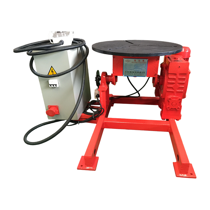 Conventional Welding Positioner Manufacturers, CompanyWuxi WeldNice Heavy Industry Technology Co., Ltd is China Conventional Welding Positioner manufacturers and company, Customization suppor...View Product →
The H beam assembly sequence also matters. In a typical H beam production line, the web is first tacked to one flange, then the second flange is added. If the web is not perfectly perpendicular, or if the flanges are not parallel after tacking, the subsequent SAW process will struggle with inconsistent arc length and variable penetration. The larger the beam, the more critical the initial fit-up jigging and the heavier the load on the self-aligning fixtures.
A structural steel takeoff cannot be completed by picking a shape that simply meets a minimum section modulus requirement on paper. The fabricator's capacity shapes the economically viable size range just as much as the structural demand does. Three practical filters apply, in this order.
1. Structural demand. The beam must resist the applied bending moment, shear, and axial load, considering the span and bracing condition. This is the engineer's responsibility. The output is a required elastic section modulus, moment of inertia, or cross-sectional area, which narrows the selection to a handful of candidate profiles.
2. Dimensional constraints. The architectural ceiling height on the beam, connection clearances at the column face, and access for bolt tightening or field welding eliminate many otherwise suitable profiles. A deep, narrow W-shape may provide the right strength but intrude into the mechanical floor space. This is where H beams with a more compact depth-to-width ratio can be preferred as column sections despite a higher weight per meter.
3. Fabrication and welding reality. This is the filter often overlooked at the budget stage. If the selected beam weighs 200 kg/m, the shop needs cranes, rotators, and manipulators sized accordingly. If the flange is 50 mm thick, the shop needs certified welding procedures for that thickness and sufficient SAW capacity. Selecting a beam that exceeds the shop's handling or welding capability forces expensive subcontracting or dangerous manual rigging of heavy sections. In building steel construction, thorough pre-construction planning of welding techniques in steel construction can prevent costly delays before a single beam is ordered.
Manual welding of a short, light beam is a skill-based task. Welding a 12-meter-long, 600 mm deep H beam with full-penetration joints is an engineering task that depends on machinery. The beam dimension dictates which automation tools become non-negotiable.
Longitudinal flange-to-web seams benefit from a welding column and boom setup paired with a SAW tractor. The column provides vertical adjustment for different beam depths, while the boom travels horizontally, keeping the torch centered over the joint. Trying to weld the same seam with a handheld semi-automatic gun results in arc wander, inconsistent travel speed, and fatigue-related defects over a 12-meter run. When this process is planned, automatic welding systems and welding manipulators form the backbone of a repeatable, documented weld quality program.
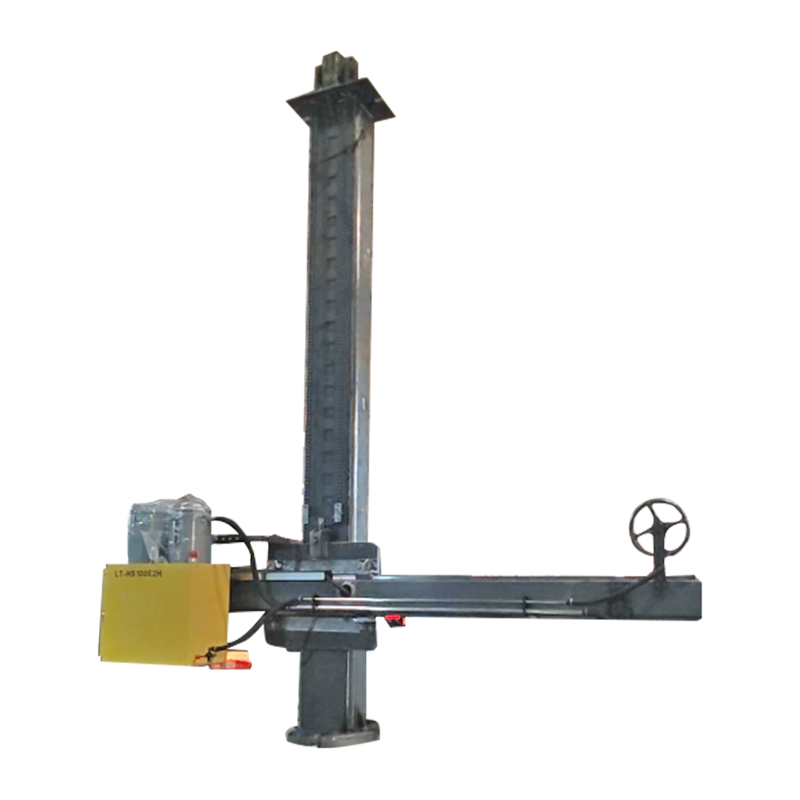 Automatic Welding Manipulator, Welding Column & Boom SuppliersWuxi WeldNice Heavy Industry Technology Co., Ltd is China welding welding manipulator supplier and wholesale welding column & boom factor...View Product →
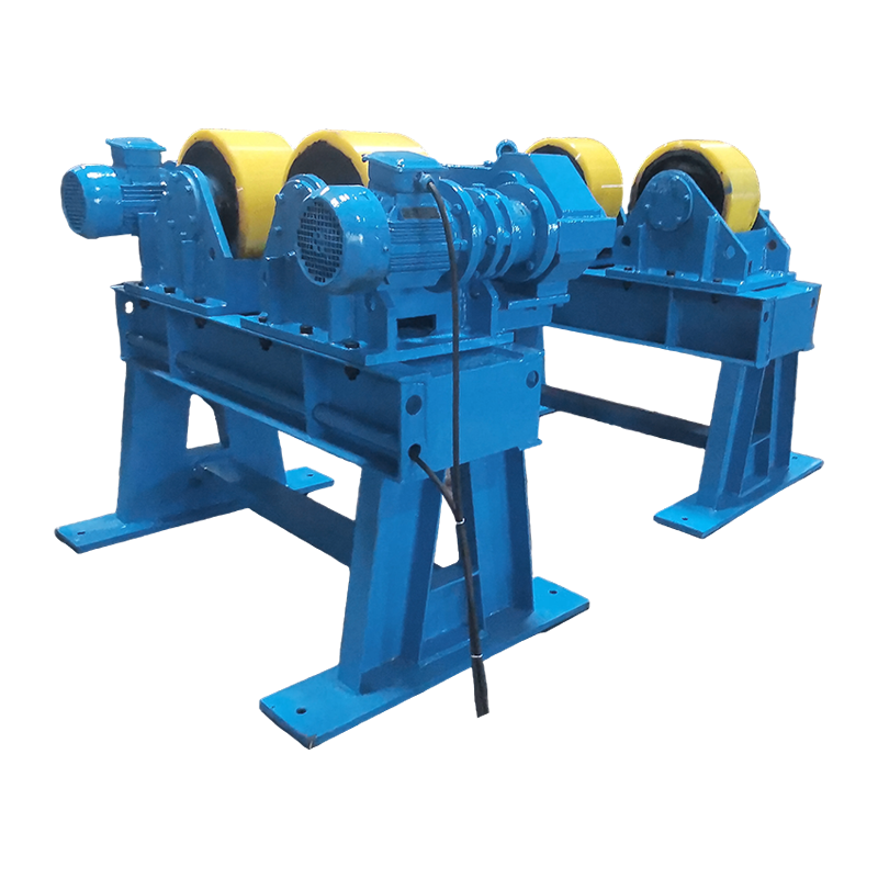
Rotation of the beam between passes is another dimension-driven requirement. A self-aligning welding rotator set allows the entire beam assembly to be turned so the welder can keep the joint in the flat or horizontal position. The heavier the beam, the more critical the roll alignment and drive torque. Self-aligning welding rotators for beam and pipe rotation adjust to varying beam widths and maintain consistent contact pressure, preventing slippage during welding.
 Custom Self Aligning Welding Rotator Manufacturers, CompanyWuxi WeldNice Heavy Industry Technology Co., Ltd is China self aligning welding rotator manufacturers and self aligning rotator company, ...View Product →
The production strategy changes with batch size. A job shop processing five different beam sizes in a week needs flexible equipment: adjustable rotator frames, positioners with variable speed control, and modular column booms that can be retooled quickly. A dedicated H beam production line, running thousands of meters of the same size profile, can justify fixed tooling depths, dedicated conveyor systems, and inline submerged arc stations. The common mistake is buying a dedicated line for mixed-batch work, or expecting manual manipulation to handle beams above a certain tonnage. The threshold where manual flipping becomes unsafe and inefficient is typically around 500 to 800 kg of workpiece weight, which many mid-sized H sections can reach in lengths over 3 meters.
Planning the welding equipment specification concurrently with the final beam size selection closes a loop that many project schedules leave open until the steel arrives in the yard. When the beam dimension is known, the required welding manipulator reach, rotator capacity, and power source output can be specified with precision rather than guesswork. That is the moment a structural shape becomes a fabrication plan.
This product is 30T Welding Rotator-Heightened, with a load capacity of 30 tons, and is suitable for welding of medium and heavy workpieces. The heigh...
See Details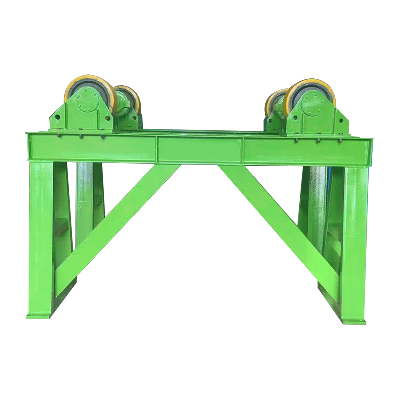
The 20T Adjustable Welding Rotator-Heightened is an industrial device specifically designed for adjusting the position of heavy-duty welded parts. Its...
See Details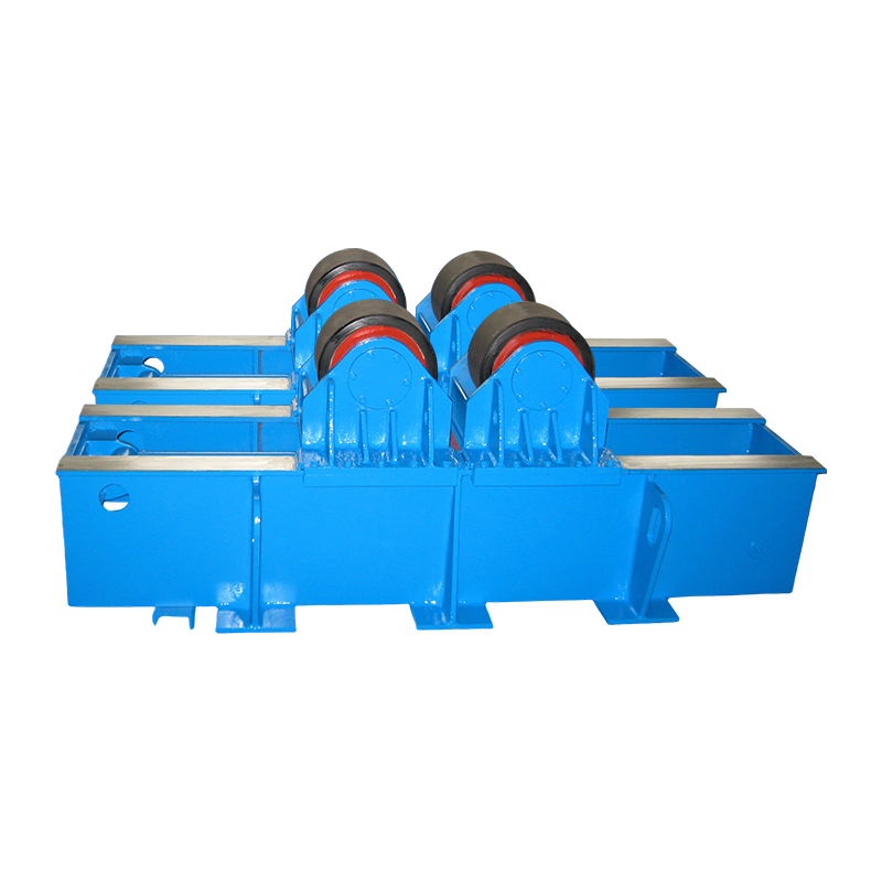
40T Fit Up Welding Rotator with Hydraulic Horizontal Pushing has a rated load of 40 tons and focuses on the assembly and welding of small and medium-s...
See Details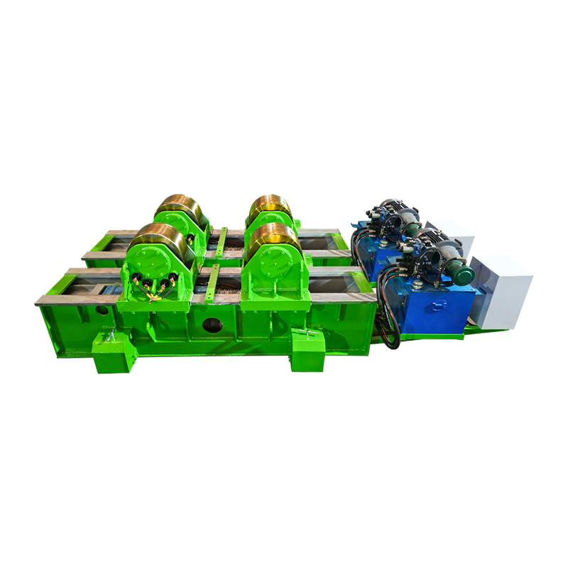
80T Fit Up Welding Rotator with Hydraulic Horizontal Pushing&Manual Orbital Movement has a rated load of 80 tons and is specially designed for but...
See Details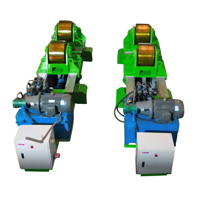
80T Fit Up Welding Rotator with Hydraulic Horizontal Pushing is a special equipment for welding and assembling large cylindrical workpieces. It is sui...
See Details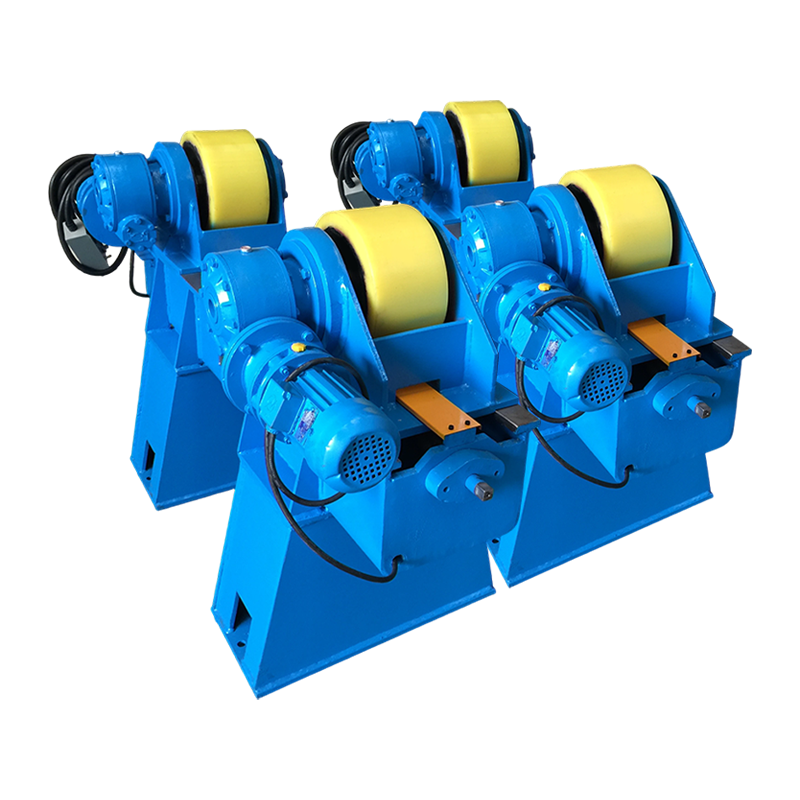
This product is 10t screw-adjustable welding rotator-heightened, suitable for welding workpieces within 10 tons. The equipment adopts a screw adjustme...
See DetailsContent
Copyright 2025 Wuxi WeldNice Heavy Industry Technology Co., Ltd. All Rights Reserved Custom Automatic Welding Equipment Manufacturers



sales@weldnicefactory.com