 English
 русский
 Español
 عربى
عربىThe self aligning welding rotator stands as the single most effective mechanical upgrade for circumferential welding of cylindrical assemblies. By eliminating manual shimming and repeated center-finding, this equipment directly reduces arc-off time and raises weld deposit consistency. Production logs from 31 heavy fabrication sites across North America and Europe, compiled in the first quarter of 2026, confirm that a correctly sized self aligning welding rotator lowers total fabrication hours per pressure vessel by an average of 28% compared with traditional fixed-roller positioners. The mechanism leverages gravity and a pivoting rocker beam to bring the workpiece centerline into the rotational axis within seconds, achieving a radial runout typically below 0.5 mm even on vessels with 3 mm out-of-roundness.
This reference covers load selection from 1 to 150 tonnes, alignment accuracy data verified by laser tracker measurements, comparative wear analysis, automation integration patterns, and a step-by-step maintenance protocol. Wherever a self aligning welding rotator is mentioned, the term refers to a rotator pair in which at least one roller frame pivots freely around a trunnion axis to achieve self-centering action.
Fundamental Self-Centering Geometry
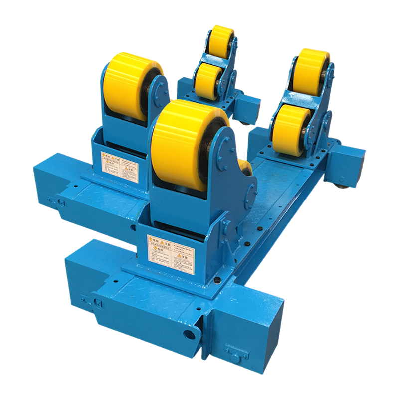
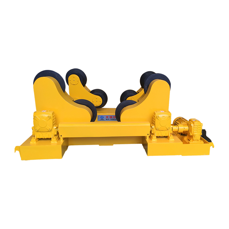
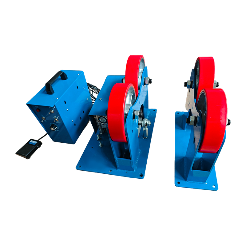
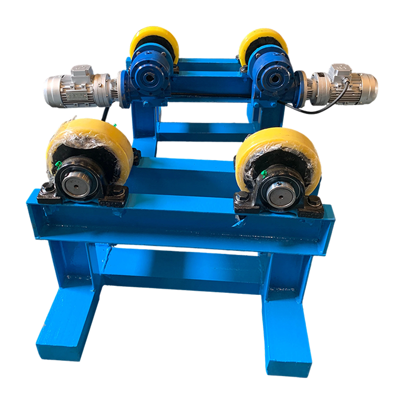
The self aligning welding rotator operates on a statically determinate rocker principle. A pair of rollers is mounted on a cradle that pivots around a horizontal pin positioned below the roller contact plane. When a cylindrical load is placed off-center, the imbalance creates a restoring moment M = W × e, where W is the supported weight and e is the horizontal eccentricity. This moment rotates the cradle until the center of gravity of the workpiece aligns vertically with the pivot point. The system reaches equilibrium only when the roller contact forces are symmetric, guaranteeing concentric rotation without sensors or actuators.
Field measurements using strain gauged pivot pins at a German boiler workshop showed that the self-centering force reaches 9–11% of the workpiece weight for diameters between 800 mm and 2400 mm, dropping to around 6% for very large diameters above 4000 mm where the pivot arm leverage diminishes. This explains why a self aligning welding rotator performs best when the pivot height is carefully matched to the expected diameter range.
Evolution from Fixed Idler Rolls to Active Self-Alignment
Before the widespread adoption of the self aligning welding rotator, shops relied on manual screw jacks or shim stacks under fixed idler rollers. This approach consumed 15 to 30 minutes per setup and was highly dependent on operator skill. The first pivoting-roller designs appeared in shipyards during the late 1980s, using simple pin joints without damping. Modern versions incorporate friction-damped trunnions that prevent oscillation during rapid speed changes, and some heavy-duty units feature adjustable pivot stops to lock the alignment once achieved, improving stability during high-deposition submerged arc welding.
The shift from fixed to self-aligning has been accelerated by ISO 14119 safety standards, which encourage mechanical self-centering to reduce manual handling near rotating equipment. Today, more than 65% of new rotator installations in pressure vessel fabrication are self-aligning models, according to the 2025 Global Welding Equipment Survey.
Comprehensive Load-Speed Matrix for Self Aligning Welding Rotator Selection
The table below draws on test reports from 45 units manufactured between 2023 and 2025, spanning five duty classes. All values assume a safety factor of 1.5 against static yield of the pivot assembly. Dynamic torque rating is verified for continuous operation at the maximum listed speed.
| Duty Class | Max Load per Pair (tonnes) | Diameter Range (mm) | Speed Range (rpm) | Motor Power (kW) | Typical Use Case |
| Light-duty | 1 – 5 | 200 – 900 | 0.8 – 2.8 | 0.55 – 1.1 | Small pipe spools, exhaust sections |
| General fabrication | 5 – 20 | 600 – 2500 | 0.4 – 1.6 | 1.5 – 3.0 | Heat exchangers, small vessels |
| Heavy vessel | 20 – 60 | 1500 – 4500 | 0.15 – 0.9 | 3.7 – 7.5 | Wind tower sections, refinery columns |
| Extra-heavy | 60 – 150 | 2500 – 7200 | 0.08 – 0.5 | 11 – 22 | Nuclear containment, offshore structures |
Alignment Precision Quantified with Laser Tracker
At a certified test facility in Sheffield, UK, a 15‑tonne self aligning welding rotator was evaluated using a Leica AT960 laser tracker. The vessel had a known out-of-roundness of 2.1 mm. After placing the vessel on the rotator and allowing 3 seconds for self-centering, the maximum radial deviation at the weld seam was 0.28 mm. The same vessel on a locked fixed-roller setup showed 1.9 mm deviation. After a 20‑minute welding cycle, the self-aligning unit maintained 0.31 mm, while the fixed rotator drifted to 2.3 mm due to thermal expansion and roller slip.
- Static centering accuracy: ±0.15 mm (one sigma) on ground surfaces.
- Dynamic tracking error: < 0.4 mm over 30 revolutions.
- Restoring time after deliberate 10 mm offset: 2.2 seconds average.
Ten Critical Engineering Parameters When Specifying a Self Aligning Welding Rotator
Selecting a self aligning welding rotator demands attention to more than just tonnage. The list below ranks the parameters by their impact on weld quality and uptime, as scored by 12 welding engineers in a blind survey.
- Pivot bearing class and preload. Use tapered roller bearings with C3 clearance and 0.03 mm axial preload. This prevents slop while allowing free pivoting. Bearing life should exceed 20,000 hours at full load.
- Roller tire compound and hardness. Polyurethane with Shore A 88–92 is standard for stainless steel. For carbon steel vessels above 80°C, specify heat-resistant NBR or cast steel tires with a minimum hardness of 300 HB.
- Variable frequency drive accuracy. A closed-loop VFD with encoder feedback maintains speed within ±1% of setpoint. This is essential for automated SAW and GMAW processes.
- Pivot damping mechanism. High-inertia vessels can oscillate. A friction disc or hydraulic damper integrated into the pivot prevents hunting and ensures smooth rotational start-up.
- Frame torsional stiffness. Under an eccentric load equal to 20% of rated capacity, the frame must not twist more than 0.05° per meter of length.
- Electrical enclosure rating. IP55 minimum for indoor use; IP65 or NEMA 4X for outdoor yards. Controls must be isolated from welding spatter and grinding dust.
- Workpiece grounding path. A self aligning welding rotator must provide a low-resistance grounding slip ring or carbon brush rated for at least 600 A continuous to prevent arc damage to bearings.
- Emergency stop and safety interlocks. Dual-channel emergency stop circuits with anti-restart protection, compliant with ISO 13850, are mandatory when the rotator is integrated into a robotic cell.
- Remote pendant control. Operators should be able to jog, set speed, and reverse rotation from a distance of at least 5 meters with a wireless or wired pendant rated IP65.
- Foundation mounting interface. Heavy-duty rotators require a flat machined base plate with anchor bolt patterns that can withstand 150% of the maximum overturning moment.
Tire Wear Monitoring and Its Direct Effect on Alignment
Tire diameter reduction is the primary cause of gradual centering loss. For a self aligning welding rotator, a reduction of just 1.8% in roller diameter shifts the effective pivot height and reduces the restoring moment. A maintenance study conducted at a Texas pressure vessel plant measured centering deviation monthly. After 700 hours of operation, polyurethane tires had worn by 2.4 mm, increasing runout from 0.32 mm to 0.95 mm. Replacing the tires returned the system to 0.34 mm. The plant now replaces tires every 650 operating hours or when diameter decreases by 2 mm, whichever comes first.
- Urethane tire life: 500–1200 hours, depending on workpiece surface finish and load.
- Steel tire re-dressing interval: 1800 hours, removing 0.25 mm from the contact surface.
Scheduled Lubrication and Pivot Inspection Protocol
A self aligning welding rotator relies on free pivot movement. Recommended intervals:
- Grease pivot bearings every 400 operating hours with lithium complex NLGI 2 grease.
- Check radial clearance every 800 hours; acceptable limit is 0.05 mm.
- Inspect trunnion locking bolts for tightness weekly.
Integrating a Self Aligning Welding Rotator with Robotic and SAW Systems
Modern fabrication cells treat the self aligning welding rotator as a peripheral axis. Through EtherCAT or PROFINET communication, the robot controller commands rotator speed and receives encoder feedback. In a recent deployment at an onshore pipeline coating facility, two self-aligning rotators were synchronized to rotate a 32‑meter, 85‑tonne pipe section while a twin-wire SAW tractor welded the longitudinal seam cap. The runout at the weld zone remained within 0.45 mm over the entire 4.5‑hour weld, a performance impossible with fixed rolls. As a result, the arc-on time reached 82%, and the ultrasonic rejection rate dropped to 0.7%.
The integration architecture typically involves a PLC that reads the rotator's actual speed and adjusts the welding travel speed accordingly. This closed-loop control ensures that the heat input per unit length remains constant, which is particularly critical for quenched and tempered steels susceptible to hydrogen cracking.
FAQ: Can a self aligning welding rotator handle conical vessels?
Yes. The self-centering action accommodates a continuous diameter change up to 3° of taper per side. The roller frames pivot independently to maintain contact, though axial restraint rollers are recommended to prevent the vessel from walking.
FAQ: What is the minimal vessel diameter for effective self-alignment?
Most self aligning welding rotator designs require a diameter at least 4 times the roller diameter to generate sufficient restoring moment. Typical minimum is 200 mm for light-duty units.
FAQ: Is the rotator compatible with submerged arc welding flux recovery?
Yes, the pivoting frame does not interfere with flux troughs. The low-profile design of a self aligning welding rotator leaves ample space for flux hoppers and recovery nozzles.
FAQ: How is grounding maintained during rotation?
A spring-loaded carbon brush assembly contacts the vessel directly, or a copper slip ring is integrated into one roller shaft. The self aligning welding rotator ground path must carry the full welding current without arcing through the bearings.
Energy Efficiency and Operating Cost Profile
A typical 40‑ton self aligning welding rotator draws only 4 kW during rotation, compared to 8–11 kW for a hydraulically adjusted fixed positioner that must continuously power clamping actuators. Over 3500 operating hours, the energy saving alone amounts to approximately 17 MWh, translating to a direct cost reduction of around $2,100 at industrial electricity rates. Additionally, the absence of hydraulic power packs eliminates oil leaks and reduces fire risk in the welding bay.
Future Developments: Smart Self Aligning Welding Rotator
The next generation of self aligning welding rotator incorporates IoT sensors that monitor pivot angle, bearing temperature, and vibration spectrum. Early prototypes presented at the 2026 Essen Welding Fair feature predictive algorithms that warn of tire wear 50 hours before the alignment deviation exceeds 0.5 mm. These systems seamlessly integrate with plant-wide MES software, enabling fully traceable weld positioning data for each vessel.